If programmers sang
Reply
I have a new post on Hackaday: Simulating The Commodore PET.
This post is part of my video blog and you can find more information about this video over here.
You can support this channel on Patreon: patreon.com/JohnElliotV
Silly Job Title: Operation Manager.
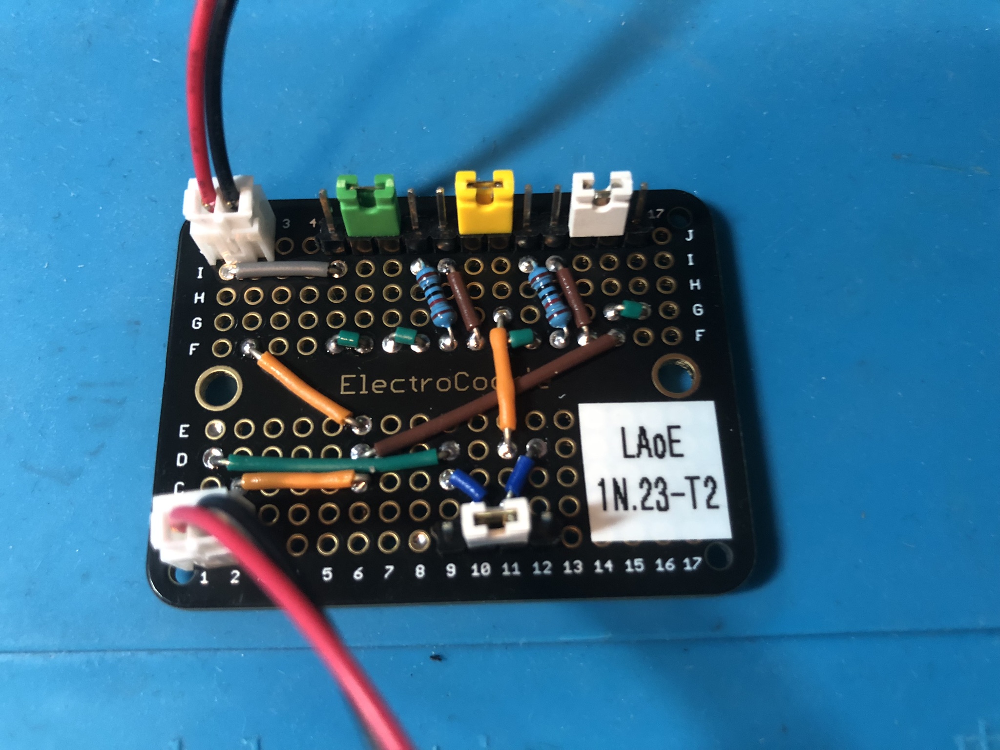
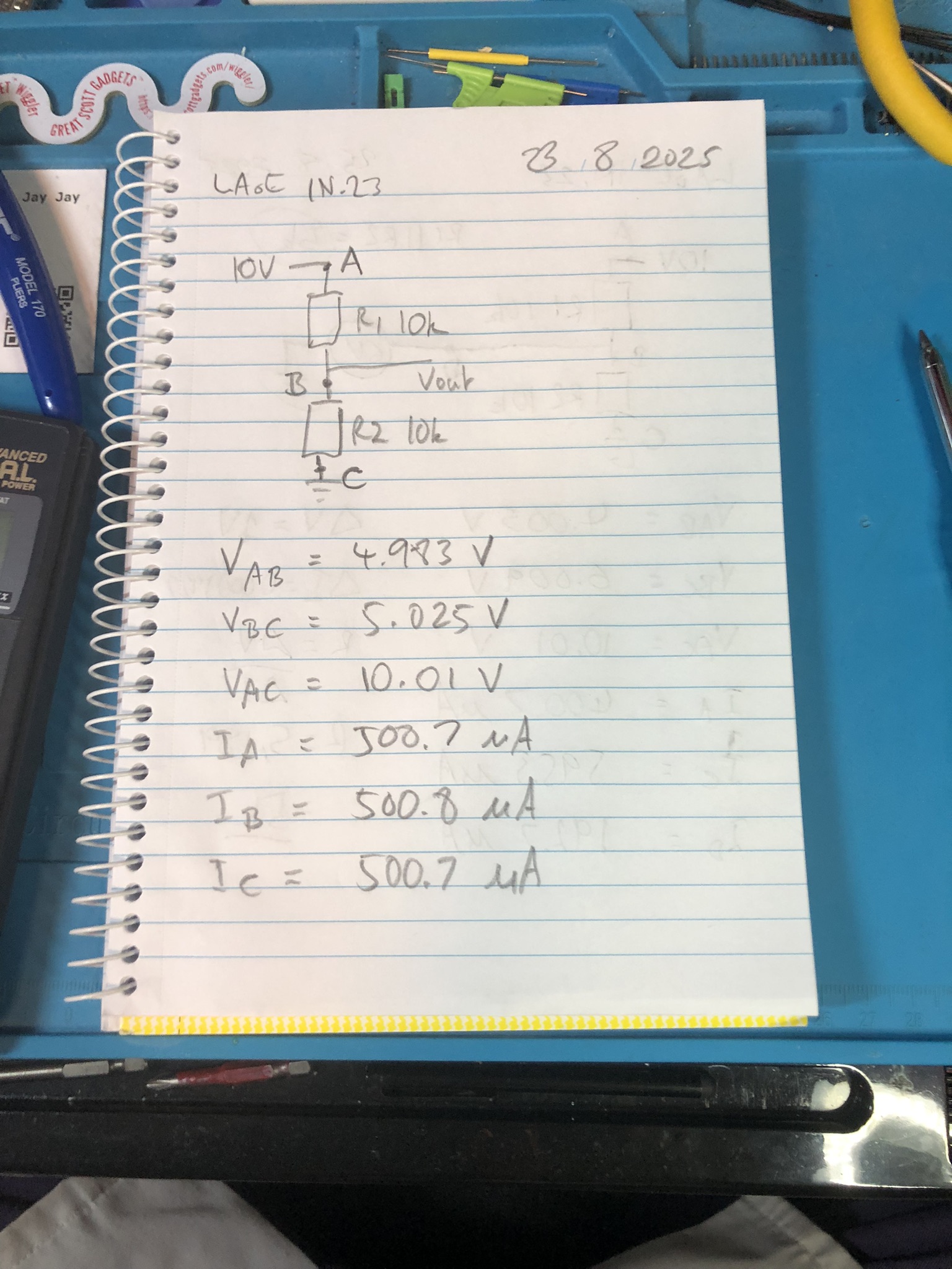
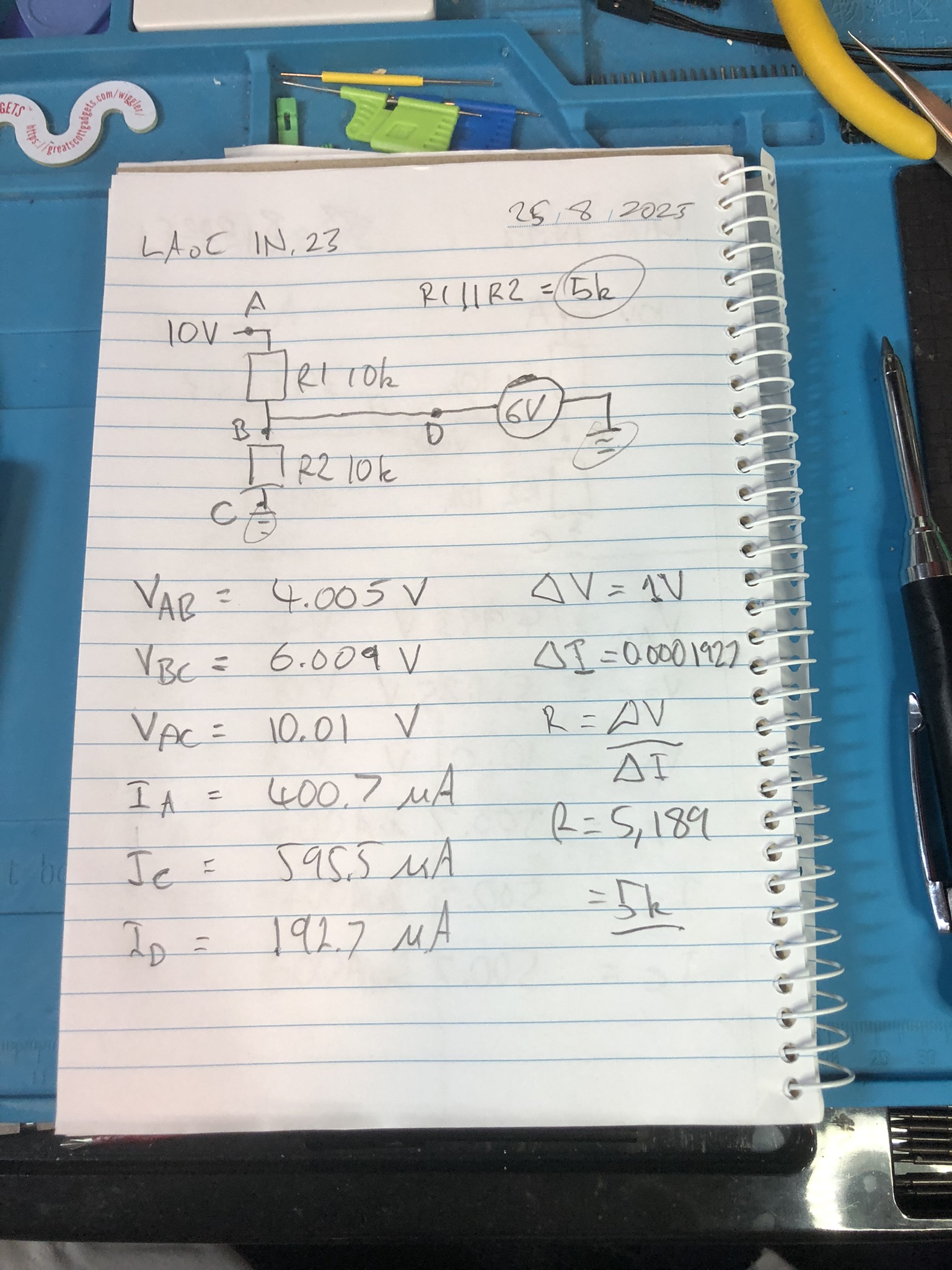
In this video we build our first circuits for Learning the Art of Electronics. The introductory video for this project is here: Introducing Learning the Art of Electronics.
The pre-reading for today’s project is up to page 17 of the course work. If you want to dig deeper there is extra reading to be found on the project home page. Note that some of my notes on the ITL Wiki are only available to people who support me on Patreon (see above).
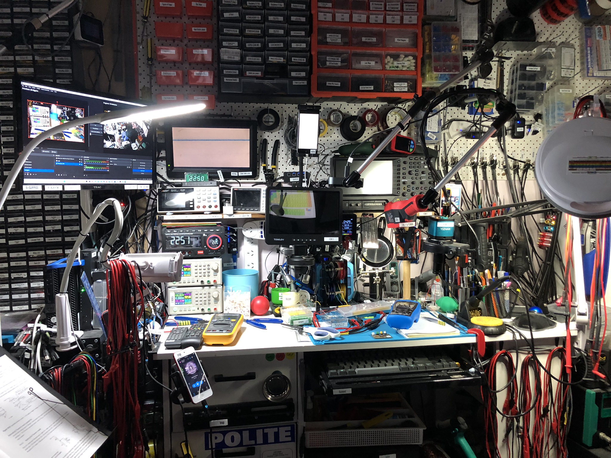
We use the METCAL PS-900 Soldering Station for soldering.
We use the EEVblog BM2257 Digital Multimeter to test voltages and currents.
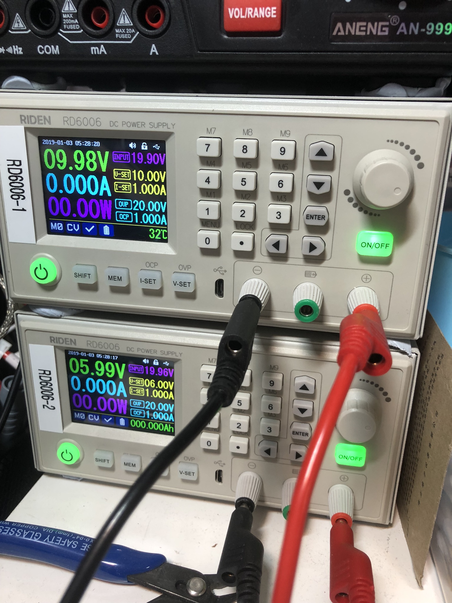
We use the Riden RD6006 Bench Power Supplies to power our test circuits.
We use the Brother P-Touch D210 Label Maker to label our circuits.
We use the WilliamKlein Music Stand to hold our book.
We use the Scotch Titanium Scissors to cut things.
We use the Carpenter Mechanical Pencil to make our notes.
We use the Hakko CHP 3C-SA Precision Tweezers for precision maneuvering.
We use the Plato Model 170 Wire Cutter to cut our wires.
Thanks very much for watching! And please remember to hit like and subscribe! :)
Following are some happy snaps of the results:
Following is a product I use picked at random from my collection which may appear in my videos. Clicking through on this to find and click on the green affiliate links before purchasing from eBay or AliExpress is a great way to support the channel at no cost to you. Thanks!
Yum Cha 9 in 1 Air Quality Meter |
Let’s go shopping!
I recently documented most of the equipment on my bench: John’s bench.
This post is part of my video blog and you can find more information about this video over here.
You can support this channel on Patreon: patreon.com/JohnElliotV
Silly Job Title: Luminary Luminar.
In this video we get Excel Tips and Tricks from Amazon and the following stuff from AliExpress:
Thanks very much for watching! And please remember to hit like and subscribe! :)
Following is a product I use picked at random from my collection which may appear in my videos. Clicking through on this to find and click on the green affiliate links before purchasing from eBay or AliExpress is a great way to support the channel at no cost to you. Thanks!
Yum Cha Blue Spudgers |
Let’s go shopping!
I have a new post on Hackaday: Solar Powered Pyrolysis Facility Converts Scrap Plastic Into Fuel.
A new post from Justin Sung: How to Effortlessly Enter DEEP WORK on Command. I assume “deep work” has something to do with Deep Work: Rules for Focused Success in a Distracted World. But basically I guess they are talking about flow.
I have a new post on Hackaday: Using The 74HC595 Shift Register To Drive 7-Segment Displays.