This was mentioned on IRC today: Nand to Tetris. Looks like fun.
Nand to Tetris
Reply

This was mentioned on IRC today: Nand to Tetris. Looks like fun.
Oh boy, this is a rabbit hole I would love to run down. Code is here:
I have some of these remote control circuits on the way from AliExpress.
I was reading the latest version of Make: Magazine, Make: Magazine, Volume 96, and I discovered this cool hardware based on the ESP32-S3: M5Stack Cardputer Adv Version. They are out of stock at the moment but I will have to check back later because I think I would love to have one of these!
I found some material from Terence McKenna that I would like to read (or listen to, or both) if I can find a few spare hours (hey, could happen!):
I want to build myself one of these: Spectrum Analyzer using Beaglebone Black and RTL-SDR.
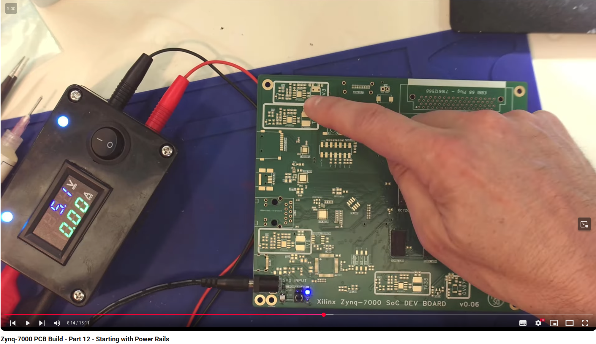
I saw this great power box over on Zynq-7000 PCB Build – Part 12 – Starting with Power Rails. I’m gonna make one! Or two!
This is great: Wireless High Resolution Scrolling is Amazing. In this video the author makes a special purpose mouse wheel for scrolling documents. I think this project is just a little bit beyond my current skill level, but maybe one day I will be able to build it.
One day I intend to Build My Own 555 Timer.
In the recent past I posted How a 555 Works as a Timer which refers to an interesting video on the topic.
In that video the speaker gives us a mnemonic for remembering the transistor schematic symbols. Referring to the direction of the arrow on the symbol the “NPN” transistor “Never Points iN”. Good to know!