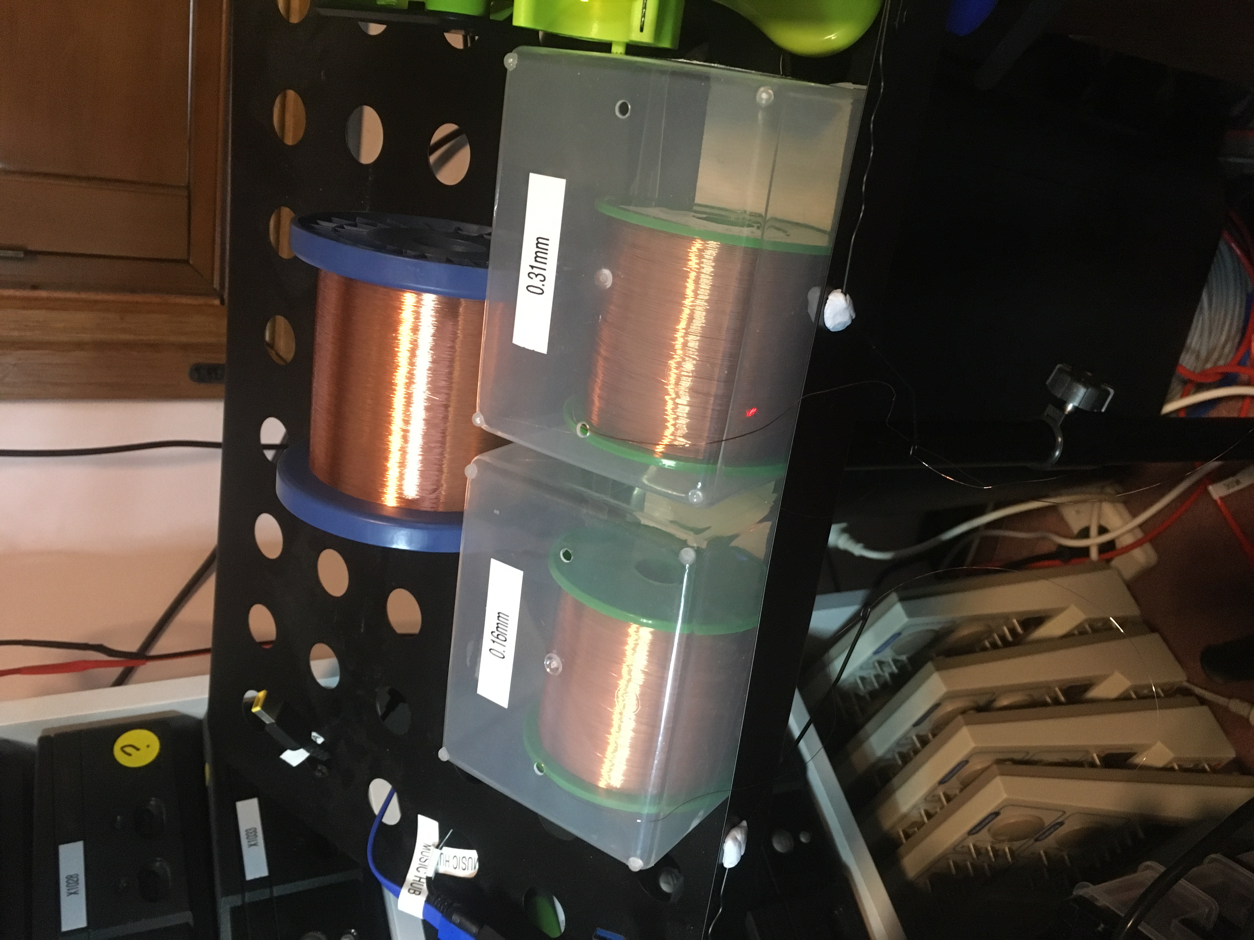
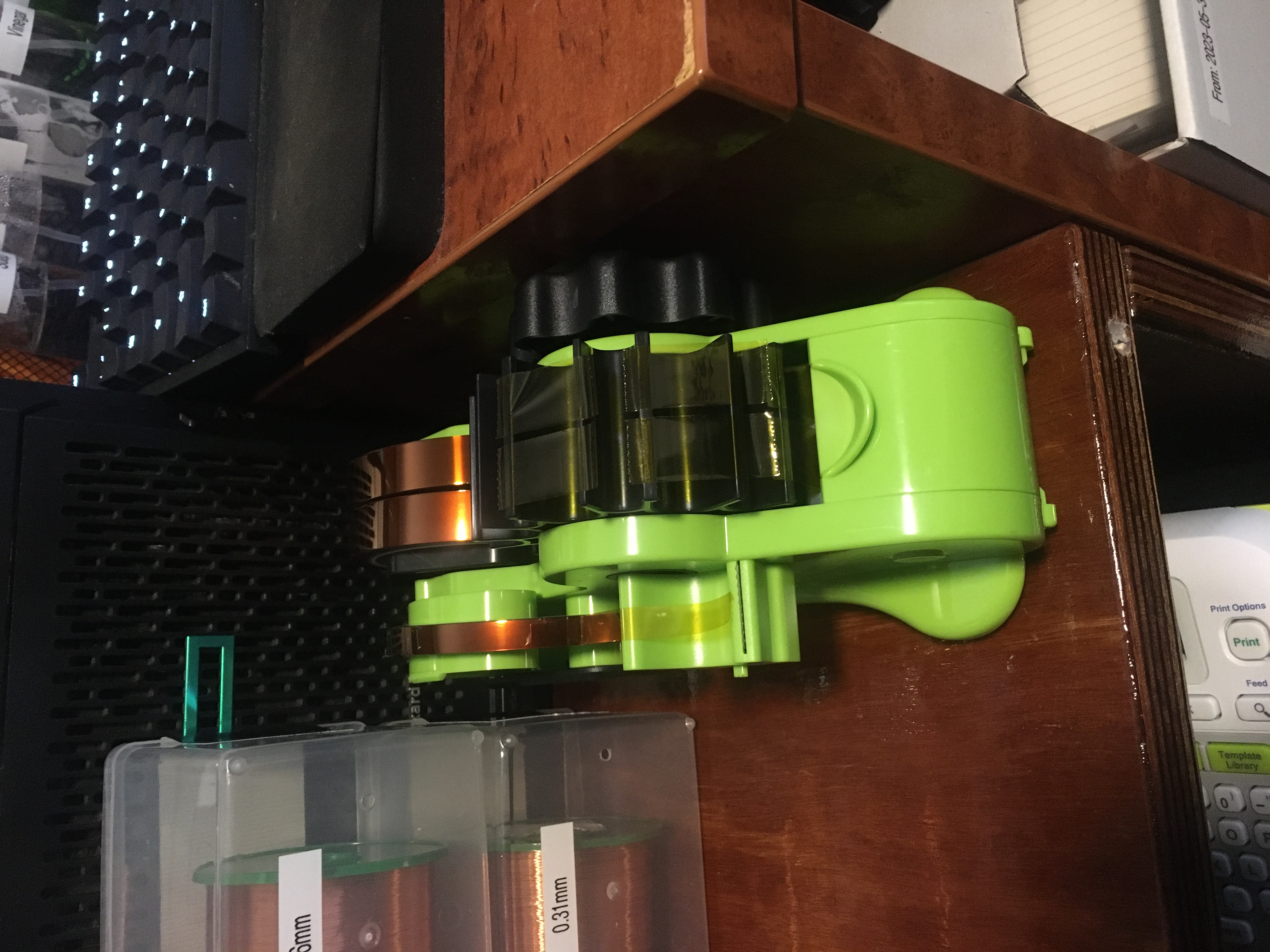
It would have been more convenient for me if the 0.07mm wire had have been on a smaller roll like the other two, but we can’t have everything. I’ve been thinking I might get some sort of wire rack, but I’m not sure where I would keep it.
I wasn’t sure exactly how I would go about cleaning enamel off the wire for soldering, so I asked ChatGPT, which gave me a number of options:
Mechanical stripping
Thermal stripping
Chemical stripping
I think what I will actually try is just tinning the ends with my soldering iron and some fresh solder and see if that will burn off just a little bit of enamel on the tips, leaving me with a tinned wire I can easily solder into place.
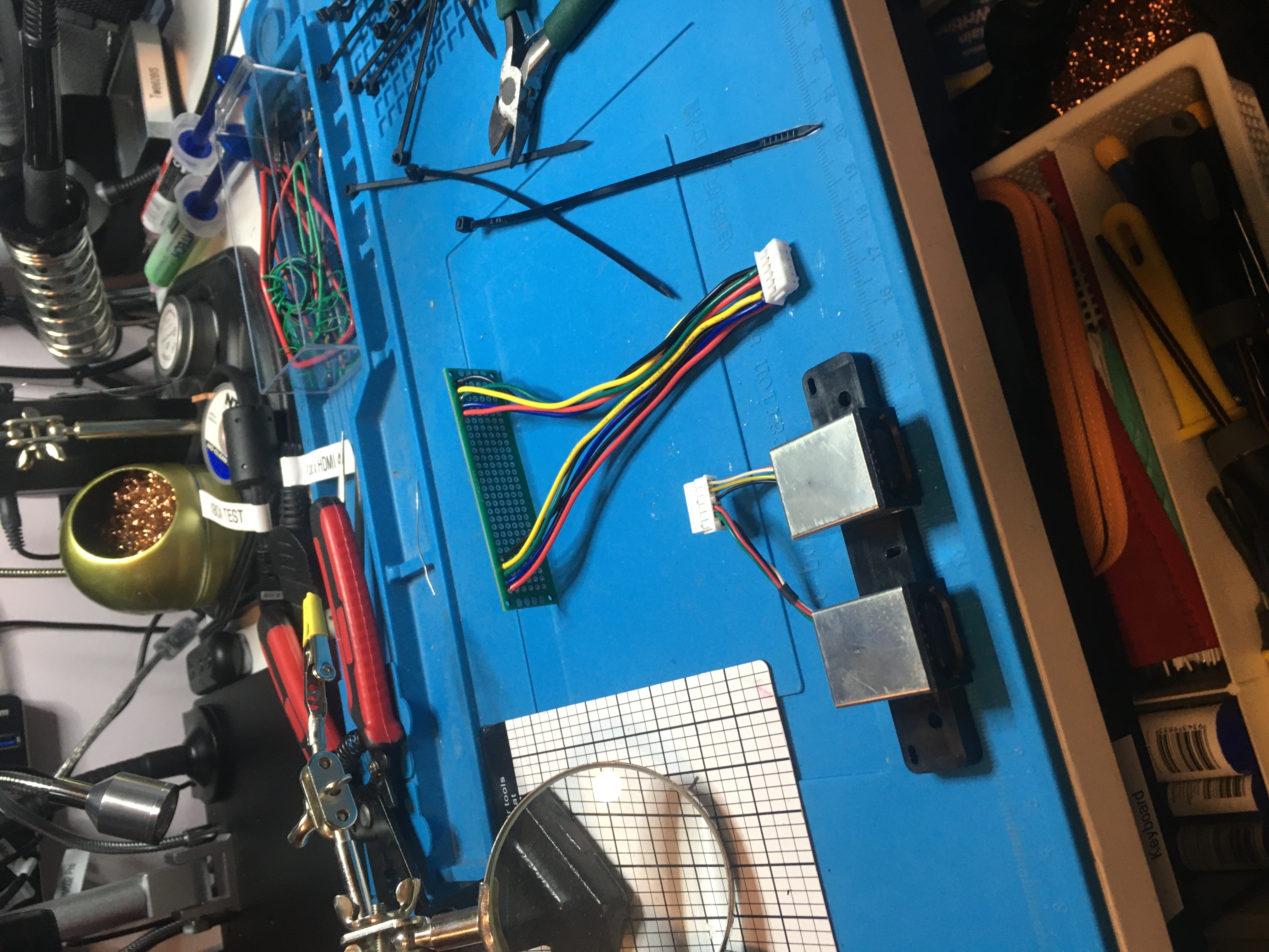
I found a good video that shows how to crimp a JST PHD connector: JST Connector Crimping. When crimping these JST connectors I use my ENGINEER PA-09 crimping tool. I use a 1.4mm crimp for the wire and a 1.9mm crimp for the insulation.
In Electrolytic Capacitor Removal NO Desoldering Required Paul Carlson says he uses lacquer thinner to clean circuit boards. On the Wikipedia article for Lacquer thinner it says these are usually mostly acetone. Personally I would only crack out the acetone if the IPA wasn’t working for me. Acetone is serious business.
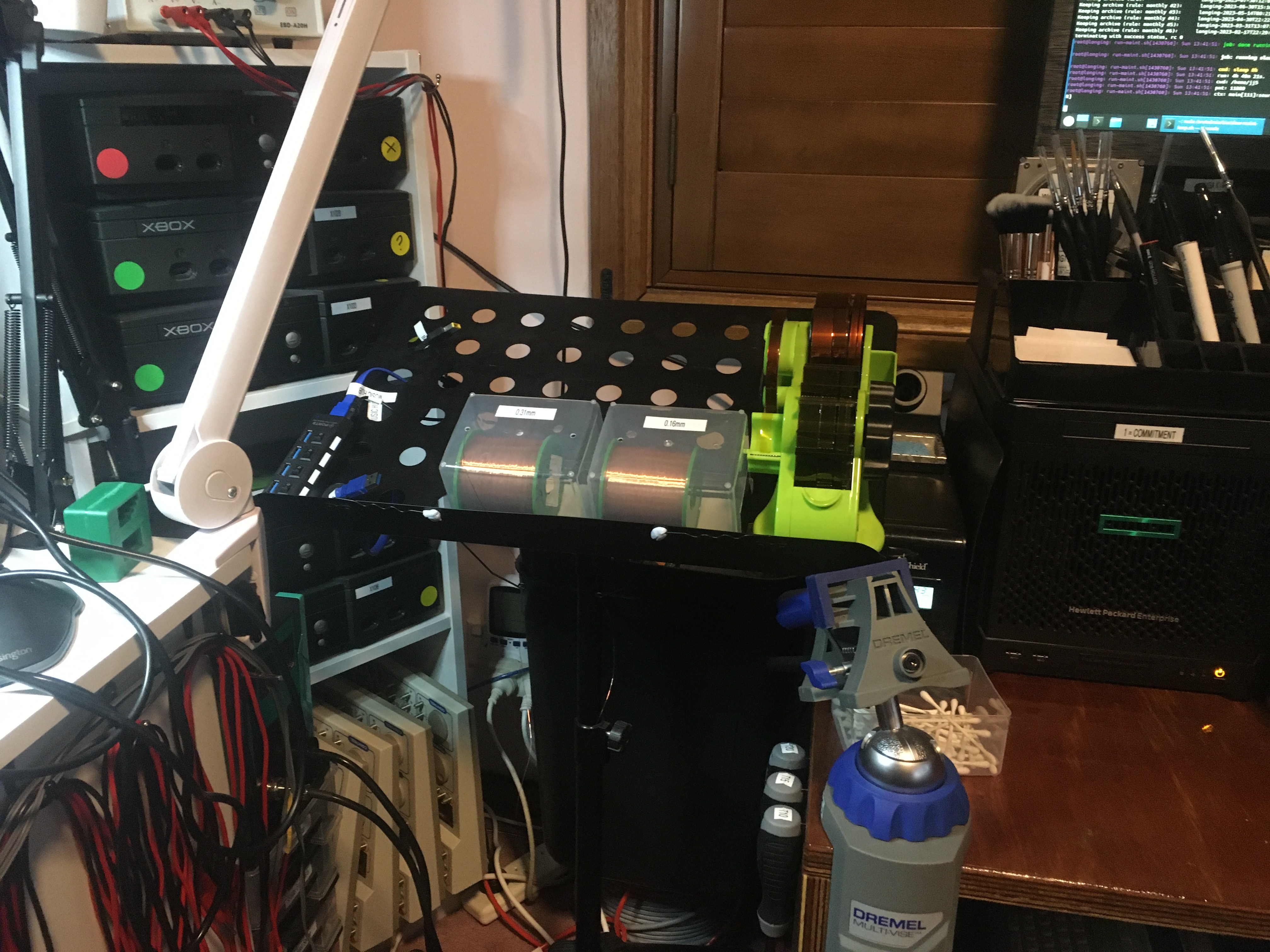
This morning I was fooling with cables for my Xbox. I want to make some breakout boards with controllers and front-panel buttons and LEDs that I can install in my bench and simply plug in when I’m working on a board.
I had a play with what I had in stock and built the cable you can see below. In the bottom of the frame is the Xbox controller connectors for two controllers, and in the top of the frame is my 10 pin JST PHD connector which I wired up just to make sure I had the right components and everything was working.
It works, but I used 22 AWG gauge wire where I probably want 24 or 26 AWG instead, so I ordered some of that on AliExpress.
I also swung by Digi-Key and stocked up on JST PHD connectors. On an Xbox motherboard (I’ve only checked v1.6 so far, I’m just getting started) you will find a 10 pin JST PHD connector for the front LEDs and power/eject buttons, two 12 pin JST PHD connectors for the controllers, and a 14 pin JST PHD connector for the DVD ROM. I got all such things:
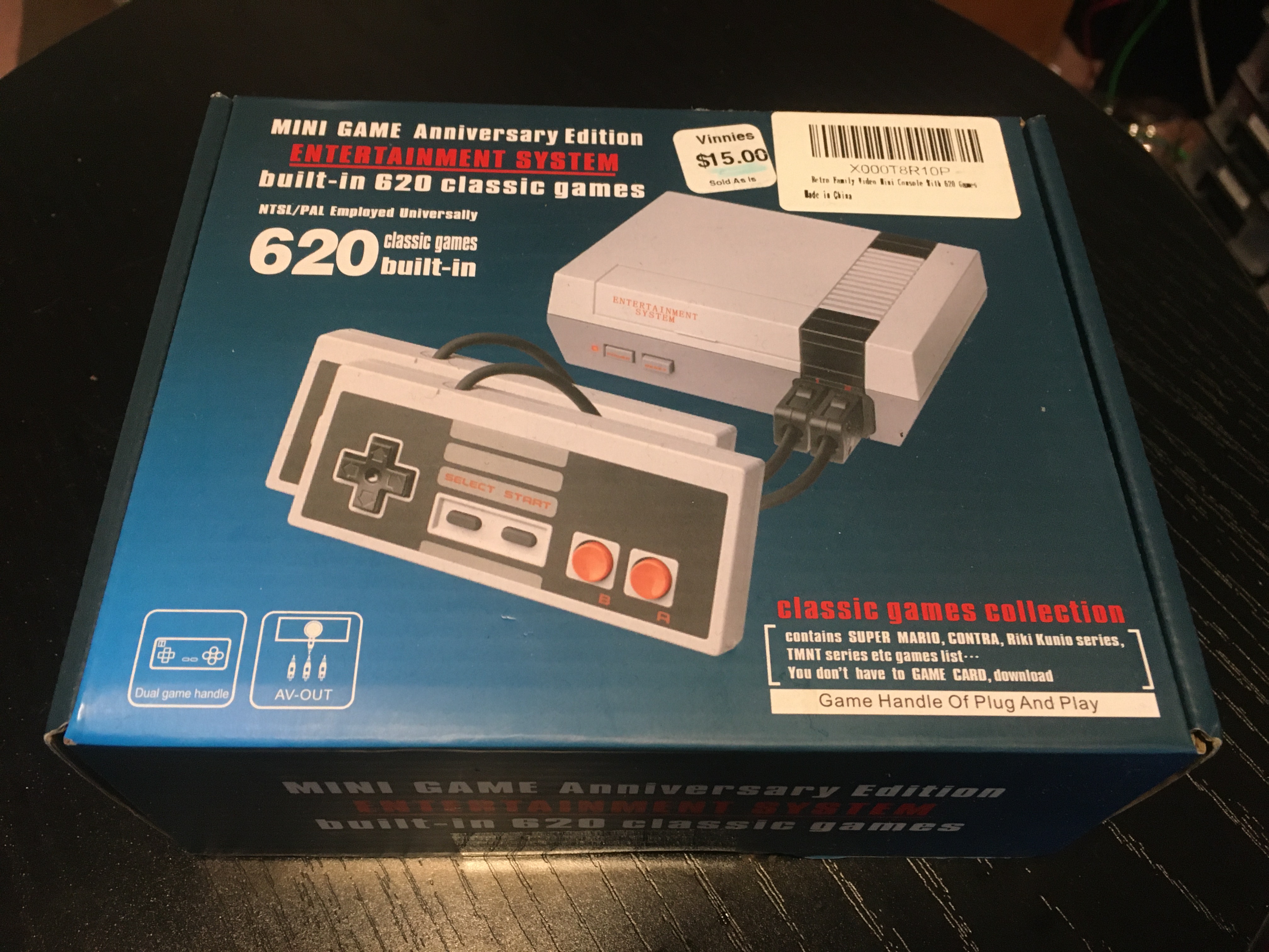
I was at the thrift store the other day and I found this retro gaming system for AU$15 (US$10). Haven’t had a play with it yet, I’m saving it for when I have some time to do the unboxing. And I didn’t want to do that until I had my new HDMI recording setup installed, but that’s done now, so I AM READY BABY.
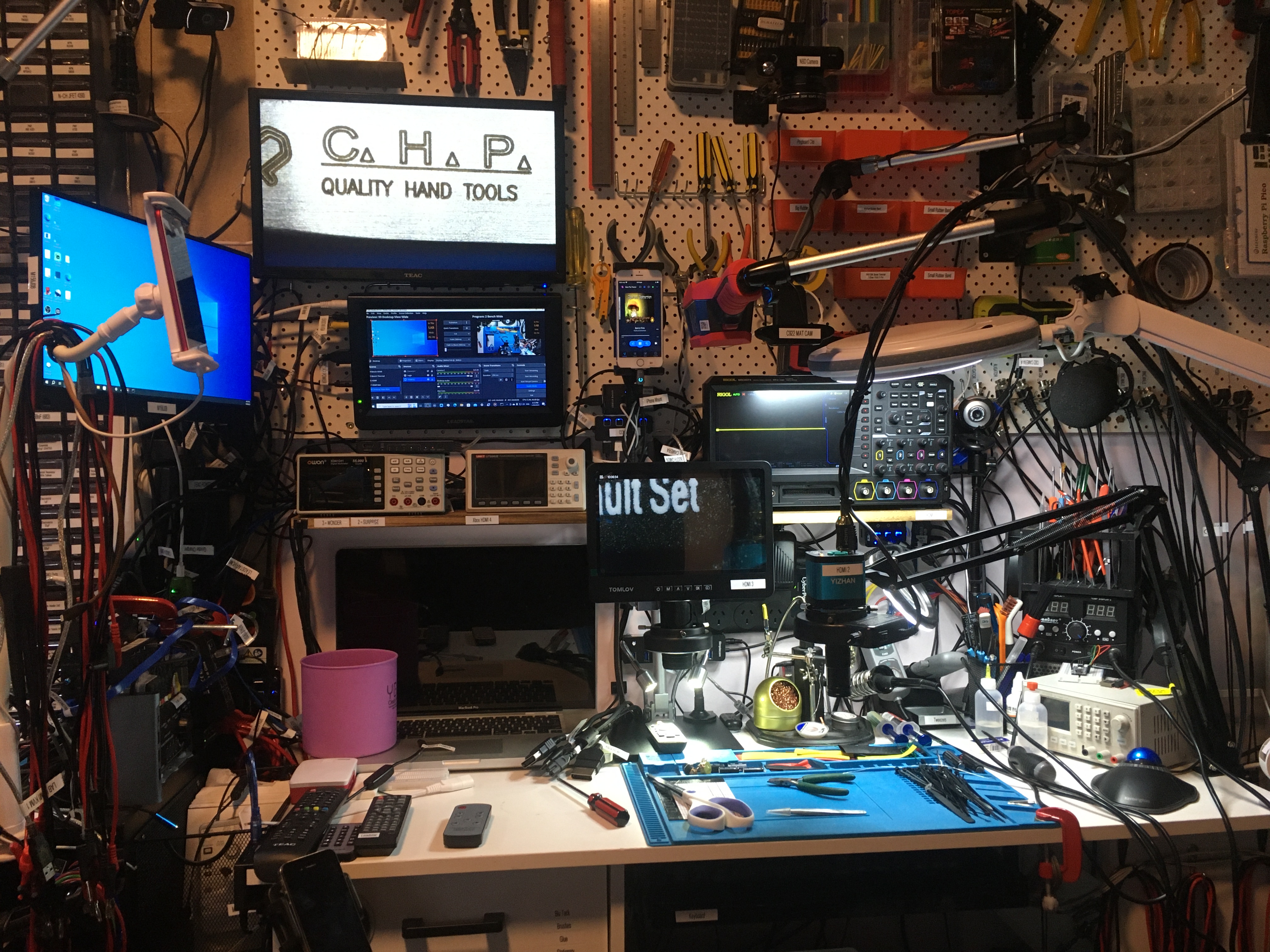
Using my new 8K 5-in 1-out HDMI 2.1 Switch I can put either of the microscopes on the top display. I can also put the Rigol MSO5074 scope and an Xbox on the top display. There is one spare HDMI port which is on the front of the device which I can use for ad hoc purposes.
Before the HDMI switch output runs into the top display (a Teac TV) it runs through a 4K Audio Video Capture Device which allows me to record the output for inclusion in my videos.
In this video I recap an old OGXbox. I also redo the thermal paste. I use my Pro’sKit SS-331 desoldering pump in anger for the first time. I spend an inordinate amount of time trying to figure out my new tools. In the end the Xbox is still broken!
I sold this Xbox on eBay but it was returned to me during the warranty period (one month) as it was faulty.
In this video I mention a trick you can do in your browser when you’re watching videos on YouTube. Ordinarily the YouTube user interface only allows you to set playback speed to 2x, but if you want to set it at 3x or higher you can do so by pressing F12 to bring up developer tools, then open the Console, and enter this code:
In this video I mention that it was in a video from Bruce from Branchus Creations that I got the recommendation to try a beveled soldering iron tip. Having given it a bit of a go and not really having great luck with it I am going back to a small chisel bit instead.
I comment in the video about how you don’t need to replace the clock capacitor on a v1.6 board, but Harcroft on the ConsoleMods.org original-xbox Discord forum reminded me that sometimes you do need to replace this capacitor.
The capacitors I use for this recapping are Chong 6.3V 3300μF Low ESR caps. Of course the board didn’t work after recapping so it’s possible these are dodgy caps.
I’m pretty sure I did damage the tip on my desoldering pump by putting the temperature all the way up to 480°C. Maybe don’t do that yourself. I believe anything over 380°C can damage iron tips (basically they melt!).
Thanks very much for watching! And please remember to hit like and subscribe!
Following is a product I use picked at random from my collection which may appear in my videos. Clicking through on this to find and click on the green affiliate links before purchasing from eBay or AliExpress is a great way to support the channel at no cost to you. Thanks!