This is a note for Future John. I found this no-nonsense video about how to program the ATtiny85 using an Arduino: How To Easily Program The Attiny85
How To Easily Program The ATtiny85
Reply

This is a note for Future John. I found this no-nonsense video about how to program the ATtiny85 using an Arduino: How To Easily Program The Attiny85
This post is part of my video blog and you can find more information about this video over here.
You can support this channel on Patreon: patreon.com/JohnElliotV
In this video we make a cable to connect a 6V battery pack with a 9V adapter to a USB Type-A female socket, which we can then use to connect a USB Type-A male through Type-B micro for powering my microcontroller.
We use the METCAL PS-900 Soldering Station to solder our cables.
We use the EEVblog BM2257 Digital Multimeter to test voltage and continuity.
We use the Horusdy Soldering Station with Hot Air Gun to shrink our heat shrink.
Thanks very much for watching! And please remember to hit like and subscribe! :)
Following is a product I use picked at random from my collection which may appear in my videos. Clicking through on this to find and click on the green affiliate links before purchasing from eBay or AliExpress is a great way to support the channel at no cost to you. Thanks!
Tungfull TH-161 Rotary Tool Accessory Set notes notes |
Let’s go shopping!
I have my ATtiny85 microcontroller installed in a HW-260 development board (purchased from AliExpress). I program the ATtiny85 with the SparkFun Tiny AVR Programmer, the setup guide is here: Tiny AVR Programmer Hookup Guide.
On the SparkFun programmer the onboard LED is PB0. On the HW-260 the onboard LED is PB1. This is the code I used to flash the HW-260 LED:
#define LED_BUILTIN PB1

// the setup function runs once when you press reset or power the board
void setup() {
  // initialize digital pin LED_BUILTIN as an output.
  pinMode(LED_BUILTIN, OUTPUT);
}

// the loop function runs over and over again forever
void loop() {
  digitalWrite(LED_BUILTIN, HIGH);   // turn the LED on (HIGH is the voltage level)
  delay(1000);                       // wait for a second
  digitalWrite(LED_BUILTIN, LOW);    // turn the LED off by making the voltage LOW
  delay(1000);                       // wait for a second
}
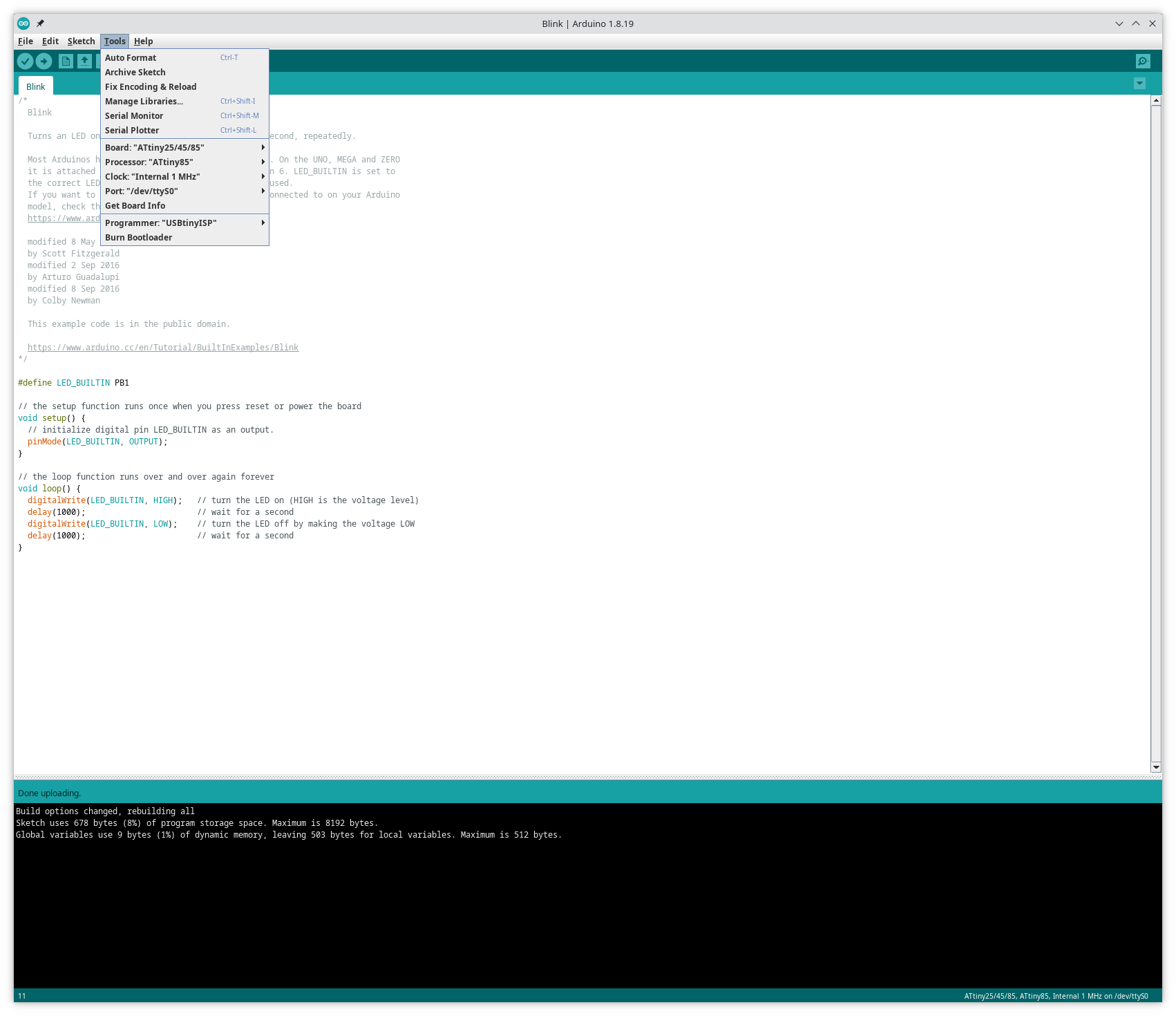
You can see the programmer settings I used in Arduino IDE in this screenshot:
Today I happened upon this ATTiny85 Quick Reference.
My mate @gwozniak recommended I check out MPLAB® X Integrated Development Environment (IDE) for programming my ATtiny85 microcontrollers. Gonna try to get around to that soon.
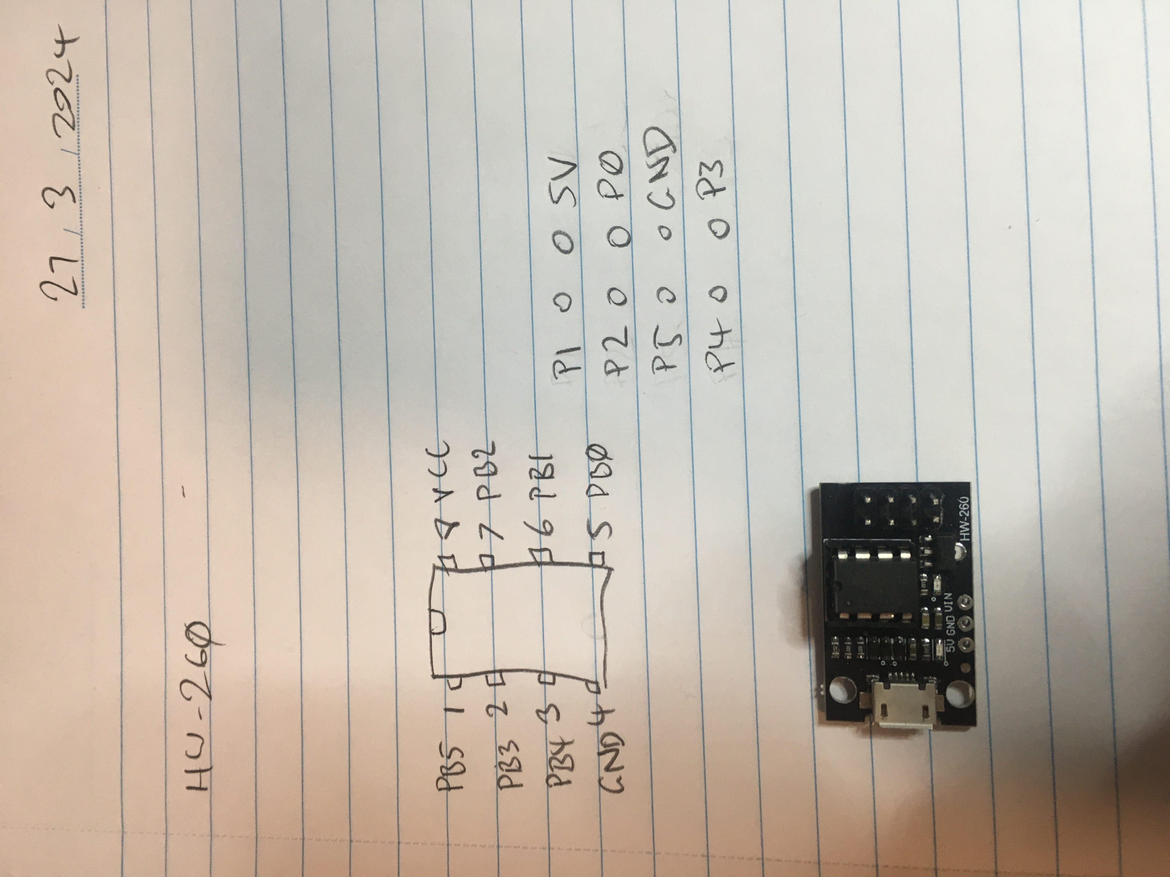
These are some notes I made about the pin-out of the HW-260 adapter boards I have for my ATtiny85 microcontrollers. I think my ATtiny45’s are also compatible. Not sure about my ATtiny13A’s.
Found myself reading about the ATtiny85 again. I keep coming back to this one. It’s an old favourite.
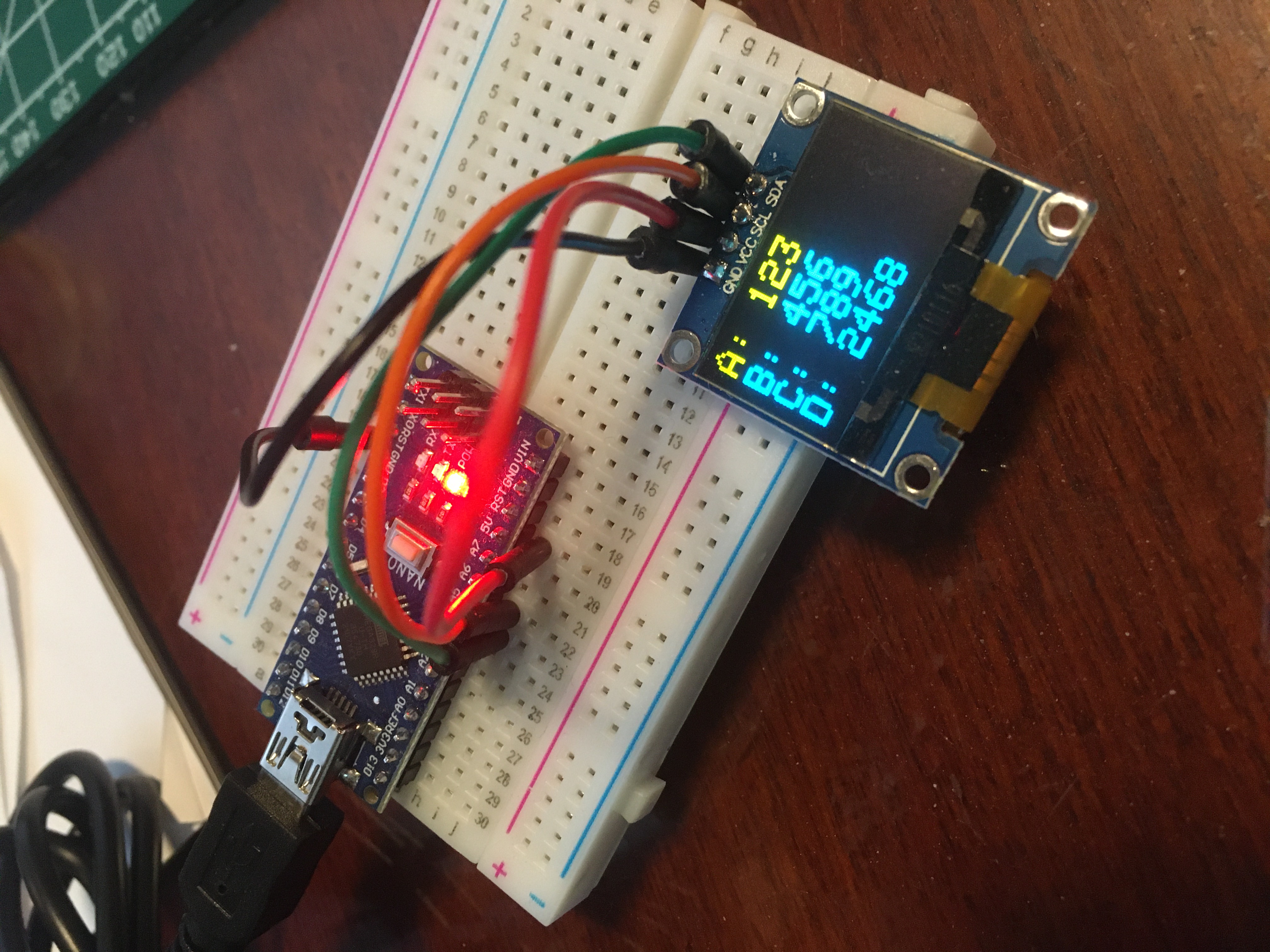
So not sure if I’ve mentioned TIS-100 on the blog before or not (update: I have). But it’s this neat computer game where you need to program a network of devices (the “Tessellated Information System”) in a pseudo assembly language in order to make a broader information system work. Anyway I was thinking about doing a hardware implementation of the system and using either some type of ATtiny (probably an ATtiny85, maybe an ATtiny45) or maybe an Arduino Nano. I did a mockup with an OLED display using a nano:
Searching for ATTINY85 over on AliExpress and sorting by popularity renders some interesting results.
I have one of these: SparkFun Tiny AVR Programmer PGM-11801. I was thinking of getting another one or two for backup, but there’s probably no need at the moment.
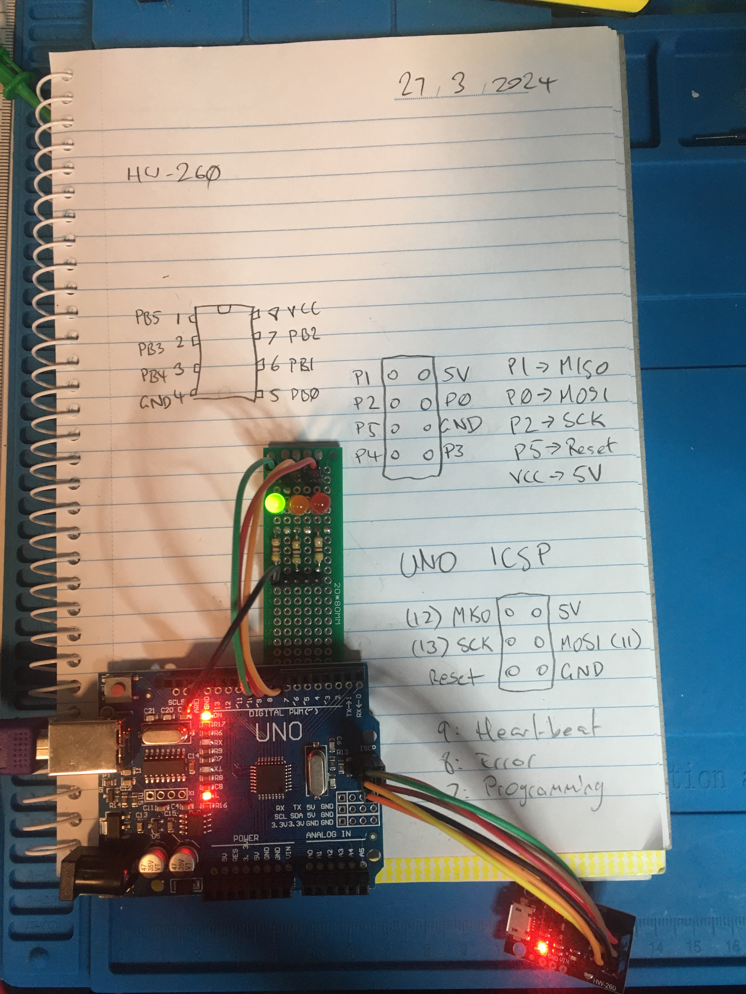
Also I figured out how to put a programmer on my Pluggable ATTINY Development Board For ATtiny13A/ATtiny25/ATtiny45/ATtiny85 Programming Editor Micro Usb Power Connector (see that link for details).