
In this photo we see three voltmeters (across the top) and five ammeters (across the bottom) attached to a voltage divider connected to a load.
30 V is applied then 2 mA flows through R1 and then splits with 1 mA going through R2 and 1 mA going through Rload. 20 V drops across R1 and there is 10 V across R2 and Rload.
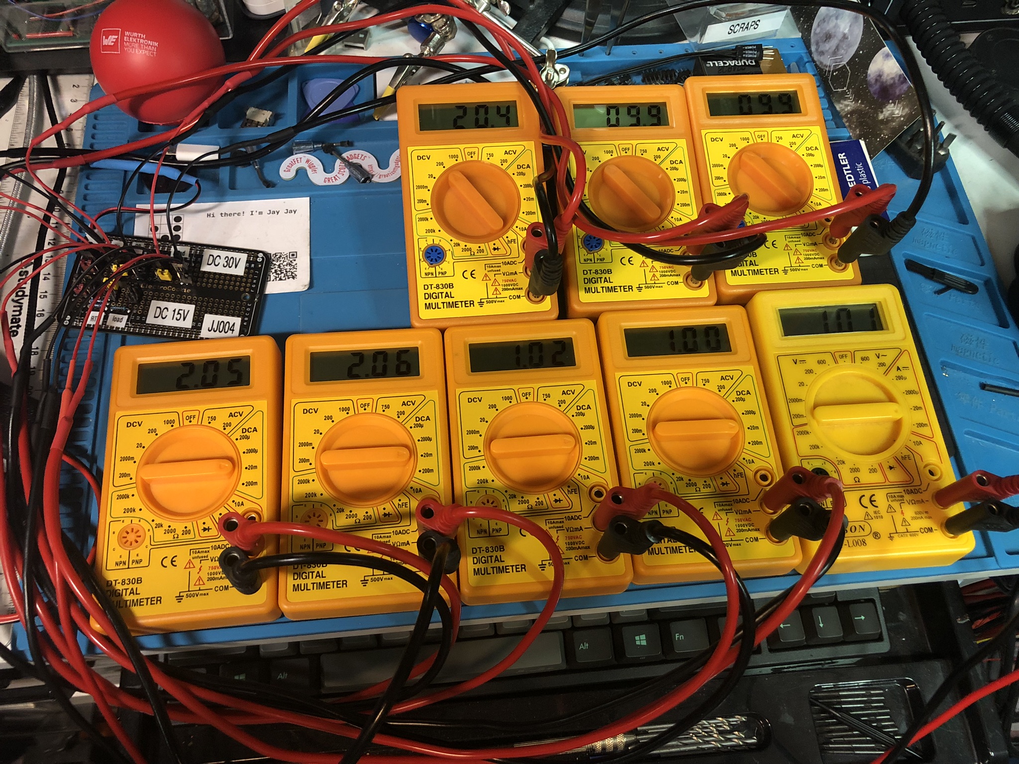
The circuit on the left in the schematic below is the one being tested. In this case R1, R2, and Rload are all 10 kΩ. As R2 and Rload are connected in parallel their effective resistance is 5 kΩ. R1 being 10 kΩ gets two thirds of the voltage because R2 || Rload is 5 kΩ getting one third of the 30 V being 10 V.
