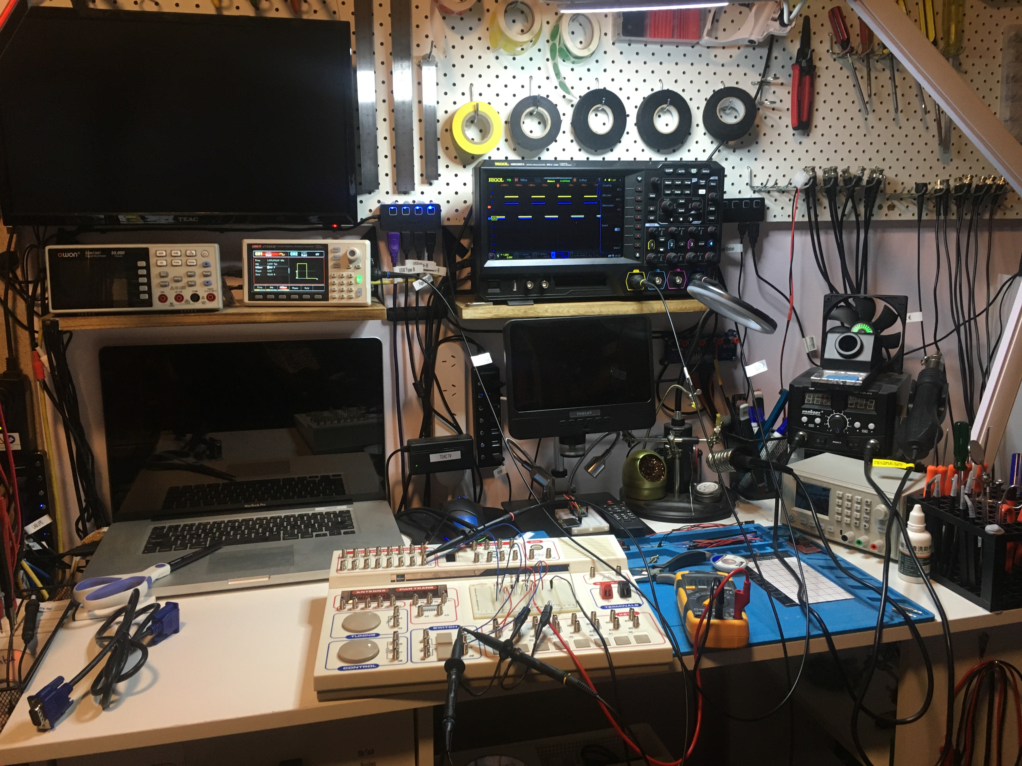
Today is the first day I have used my signal generator, my scope, and a breadboarded circuit, at the same time. Used my multi-meter with its new cables too!
Thanks to my friend Raz for his help. <3

Today is the first day I have used my signal generator, my scope, and a breadboarded circuit, at the same time. Used my multi-meter with its new cables too!
Thanks to my friend Raz for his help. <3
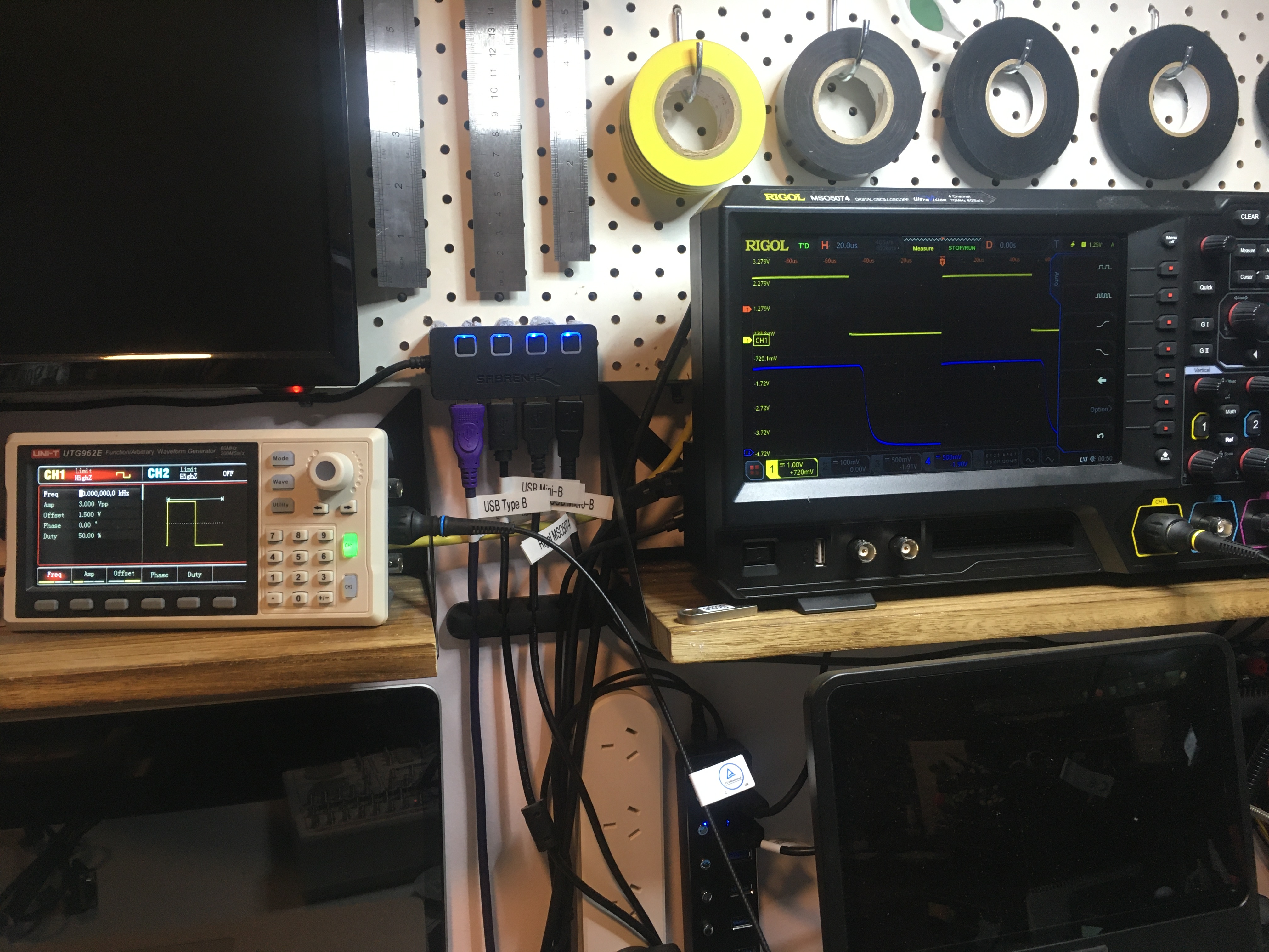
So I pumped a 1 kHz square wave into my DTL OR gate and observed the behaviour with my scope!
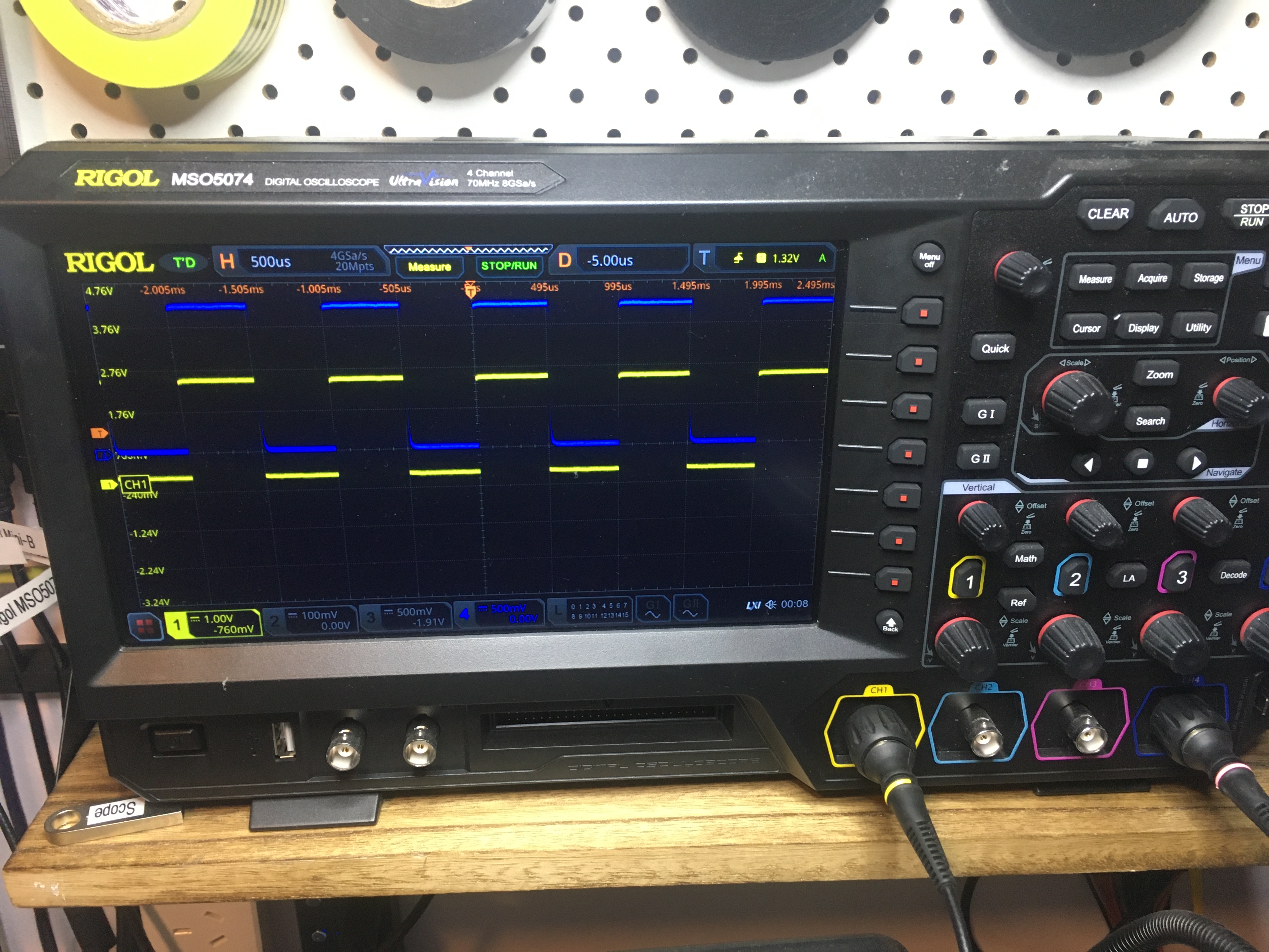
The square wave is in yellow, and the blue is the output signal.
You can see the output doesn’t drop back to zero quite as fast as the input.
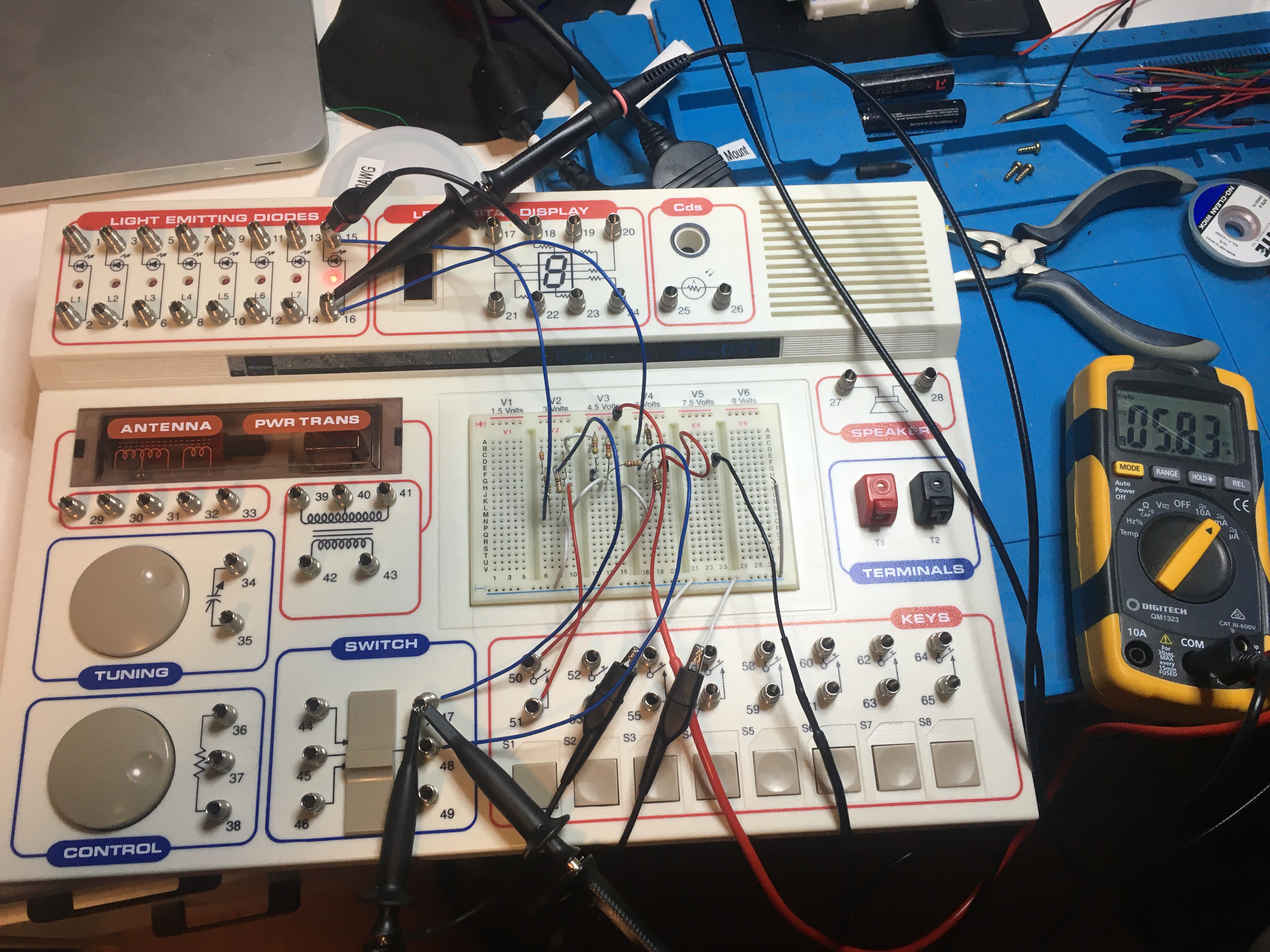
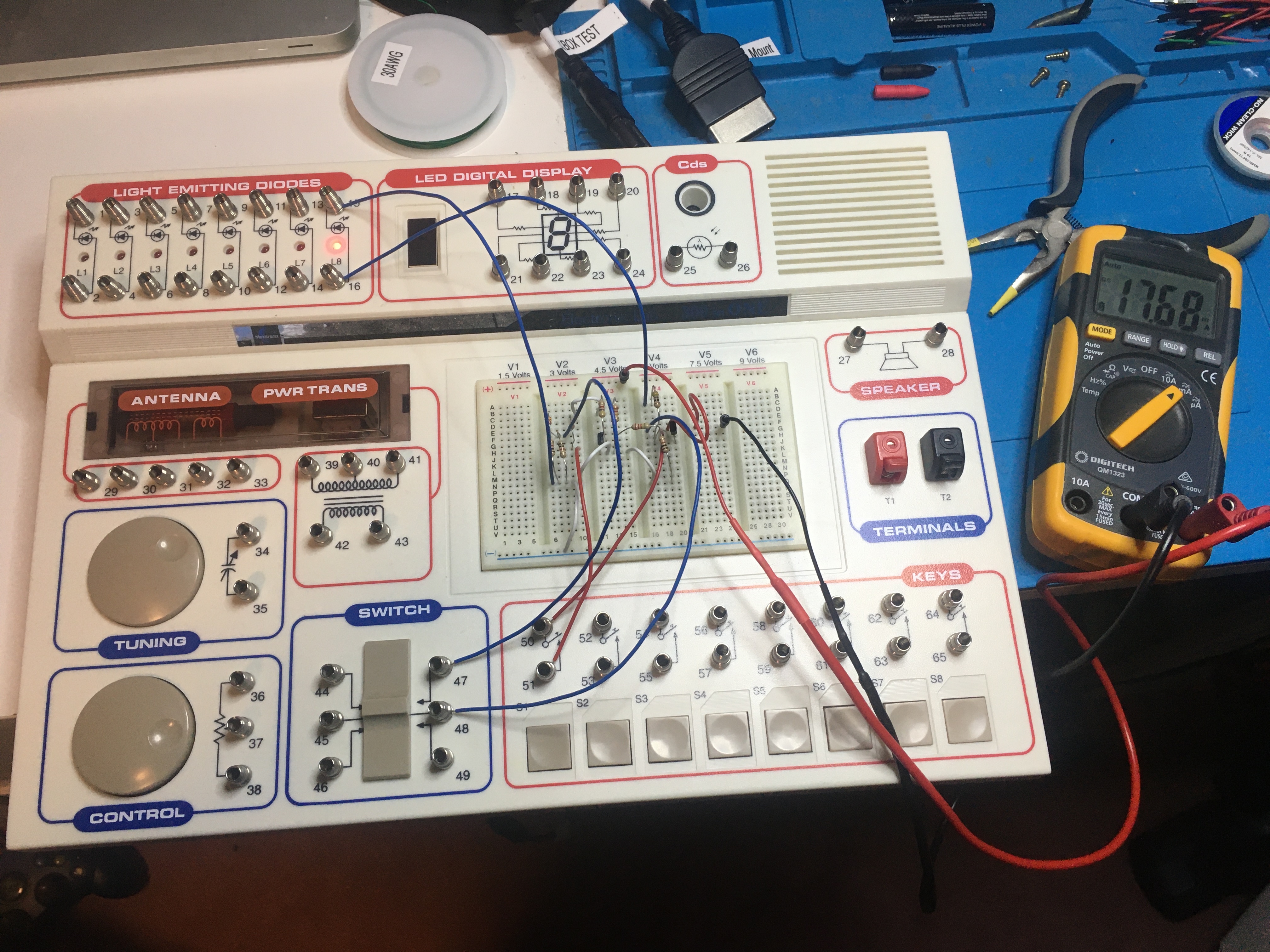
You can see on the multi-meter to the right that the current draw is about 5.83 mA. That’s consistent with my earlier measurements given a duty cycle of 50%.
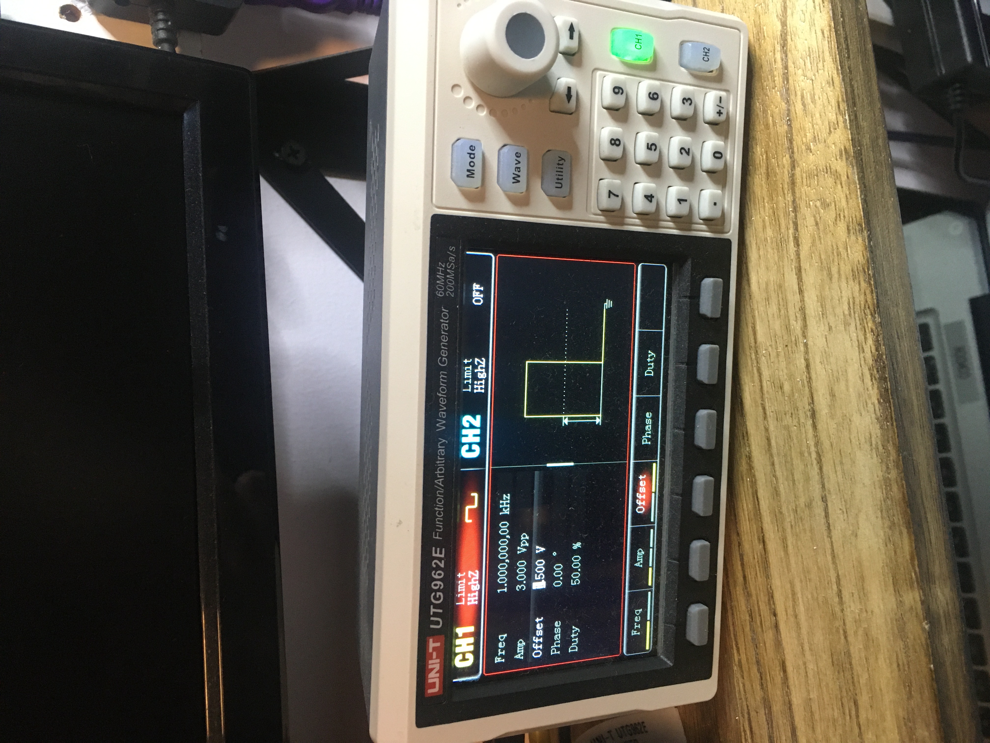
And you can see in the following photo that the frequency response of the circuit is rubbish. If you go much above about 10 kHz the output just stays “on”.
I found a good article explaining how pull-{up,down} resistors work and how to calculate appropriate values: Pull-up Resistors and Pull-down Resistors Explained.
So I used my new cables in anger. I took a reading of the current draw on 300in1 project 155 that I was working on the other day. Will be able to experiment with the effect of using different resistors (and none at all).
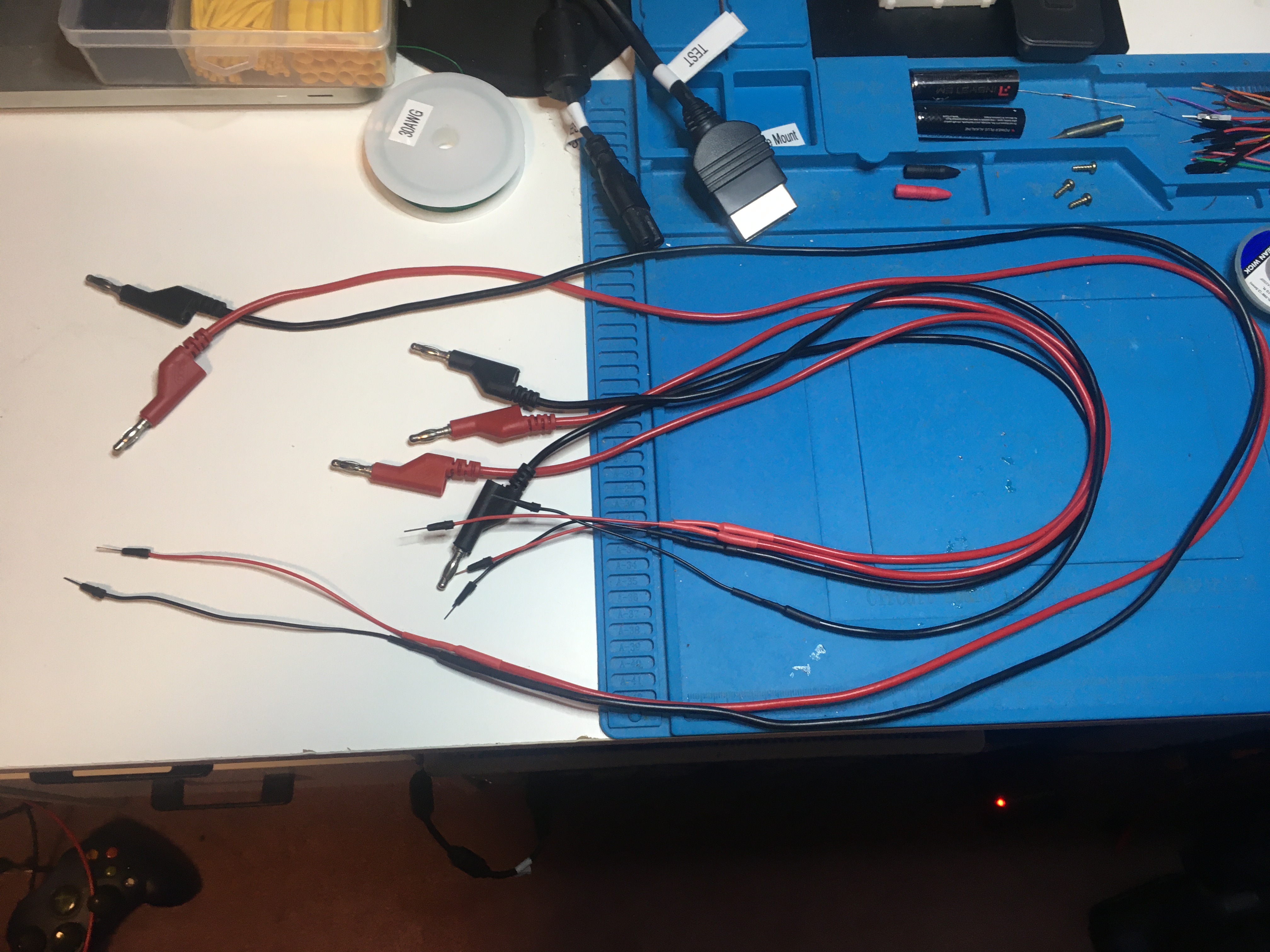
Made some cables. Male banana plug into male jumper wire. Got some of these and cut them. Made a pair of long ones and two pairs of short ones. This is so I can plug my multi-meters into my breadboards. Gonna do the same thing with some BNC attached coax so I can hook up my scope and with some female DuPont cables so I can plug into male pin headers.
Today I got myself two of these RG316 coaxial cables. Other choices were RG58 and RG174 options. I found this discussion on reddit which suggested that for my application (connecting my bench scope to circuits for testing) any of them will probably do. I got two 4 meter cables, so when I cut them in half I will have four 2 meter cables.
Some notes about how spectrum is allocated in the USA: The United States Frequency Allocation Chart
I must, must, must not get involved in radio. I would love to, but I don’t have enough time or money! Gotta stay digital… :P
Some interesting rules of thumb for user interface design: Visual design rules you can safely follow every time.
One note I want to make for later on is to use #222222 instead of #000000 and #F2F2F2 instead of #FFFFFF.
An interesting write up concerning a shanzhai knock off: Anatomy of a cheap USB to Ethernet adapter.
So “SAT” can stand for SCSI / ATA Translation.