Diode Experiment | Project 3/10 | Maxitronix 10in1 | Learning Electronics In The Lab With Jay Jay

This post is part of my video blog and you can find more information about this video on this show’s homepage which is here.

You can support this channel on Patreon: patreon.com/JohnElliotV

In this video I do the third Maxitronix 10in1 Electronic Project Lab project: Diode Experiment.

When I looked at the resistor on the bottom I thought it was red – brown – black – gold which would have been 21Ω but I think I misread brown and that was actually purple which would be 27Ω which stacks better with the two measurements I made both of which said 27Ω.

In the video we examine the forward voltage of our germanium diode and get various readings. Typically a germanium diode should be around 0.3V versus silicon diodes which are usually around 0.7V.

The component testers we use are these:

On the FNIRSI component tester the Ir is the “reverse current”, also known as the “leakage current”. This is the small amount of current which flows through the diode when it is reverse biased (that is, basically, connected the wrong way around).

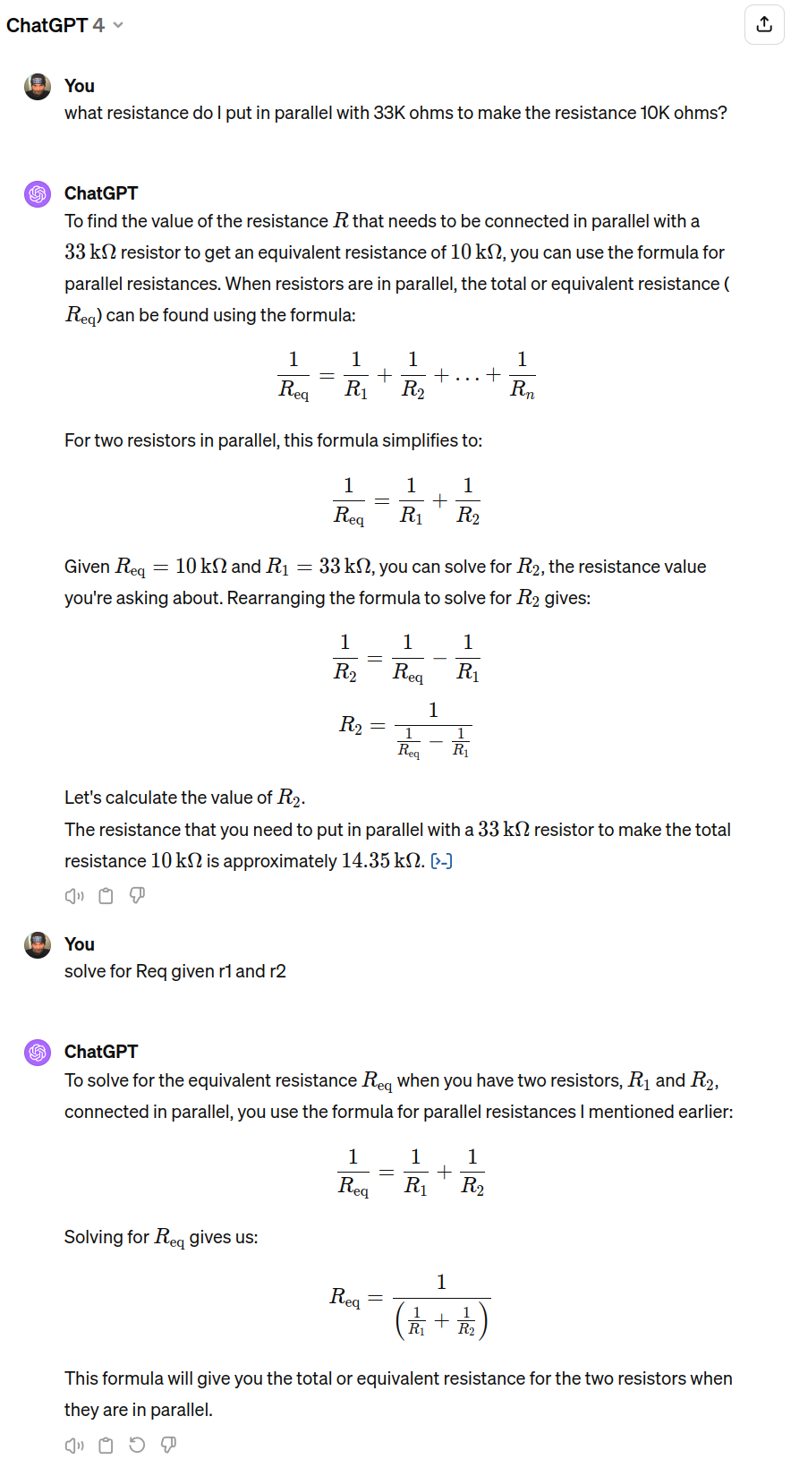
I asked ChatGPT a few questions about diodes and their specifications which you can read here: Germanium Diode Forward Voltage if you’re at all interested in such things. Of course you should be doubly suspicious of anything you read on the internet. :)

The really amazing learning for me in this experiment was how hot the germanium diode got versus the lamp, which was so surprising. Just goes to show how good an idea it is to actually do experiments and measure things! The thermal imager we used was the UNI-T UTi260B.

Also I think I’m coming around to the view that an oscilloscope is a pretty poor voltmeter. My oscilloscope is an MSO5074 70MHz 4 Channel MIXED SIGNAL OSCILLOSCOPE and I love it but I think in future I will limit my use of the oscilloscope to situations where I’m actually dealing with some sort of oscillator. I think simple digital multimeters would have been better test equipment to use for the kinds of readings I was trying to take in this experiment.

I hope you enjoy the video. Stay tuned for the upcoming projects. If you’re interested in seeing them don’t forget to subscribe!

Also, if you’re interested in getting any of these Maxitronix kits yourself the best place I know to look is on eBay. Let me know if you find them somewhere else!

Thanks very much for watching! And please remember to hit like and subscribe!


Following is a product I use picked at random from my collection which may appear in my videos. Clicking through on this to find and click on the green affiliate links before purchasing from eBay or AliExpress is a great way to support the channel at no cost to you. Thanks!

aToolTour Black Hexagon Deburring Drill BitThis is an image of the product.notes

Let’s go shopping!

Propagation of electricity

Thanks to Craig for referring me to Brian Haidet’s AlphaPhoenix channel.

I found the following four videos on the AlphaPhoenix channel explaining various aspects of the propagation of electricity, which goes some way to explaining how the high impedance headphone might work in my 10in1 2/10 project.

While watching the videos I discovered that Brian’s oscilloscope is a Siglent SDS1104X-E (100 MHz) Oscilloscope, a pretty nice looking bit of kit!

6 Horribly Common PCB Design Mistakes and AppCAD

Today I enjoyed watching 6 Horribly Common PCB Design Mistakes and the follow-up video Design Mistakes You Must Avoid on Your New Electronic Product.

In the first video I learned about AppCAD Design Assistant which is a free tool which boasts a broad bunch of features (and, particularly, it can help you design an antenna on your PCB):

  • S-Parameter Analysis and Plotting
  • Active Circuit Bias Design
  • Cascade Noise and IP3 Analysis
  • Transmission Line Analysis
  • Signals and Systems
  • Complex Math Engineering Calculator

I haven’t used AppCAD yet, but I will check it out soon.

BIOS settings for ‘verve’

I went hunting in the BIOS for ‘verve‘ which has a ASUS PRIME B550M-A motherboard and I found I needed to change two settings.

The first setting was Advanced -> CPU Configuration -> SVM Mode = Enabled. This enables AMD-V and allows the CPU to function in a hypervisor.

The second setting was Advanced -> Onboard Devices Configuration -> USB power delivery in Soft Off state (SS) = Disabled. This fixes the problem with the power button not working as discussed here: Earth leakage hack.

Earth leakage hack

Happy New Year! Best wishes to all my friends for 2024.

I have this weird problem with my new studio computer ‘verve‘. When I press the power button, it doesn’t turn on. It does have 15 USB cables plugged into it, and quite a number of those are powered, which seems to affect the system.

The power for most of the devices on my bench goes through a PowerShield Defender 1600VA UPS battery, and then through an Arlec PB91 Residual Current Device (RCD).

The RCD has a test feature so you can press the button on the RCD and it will trip the safety which will disconnect the power. If I do this most of the equipment on my bench will turn off (but, importantly, not my workstation ‘verve’) including all the powered USB devices which are interfering with my computer.

After I trip the RCD I can power on my computer, and then once it’s powered on I can reset the RCD and bench power is restored. It’s a bit fiddly but at least it works!