I took some time today to update the Affiliate Links page on the blog. Now there’s a table which catalogs most of the interesting equipment in my lab along with a link (or two) to where you can buy.
Affiliate Links
Reply

I took some time today to update the Affiliate Links page on the blog. Now there’s a table which catalogs most of the interesting equipment in my lab along with a link (or two) to where you can buy.
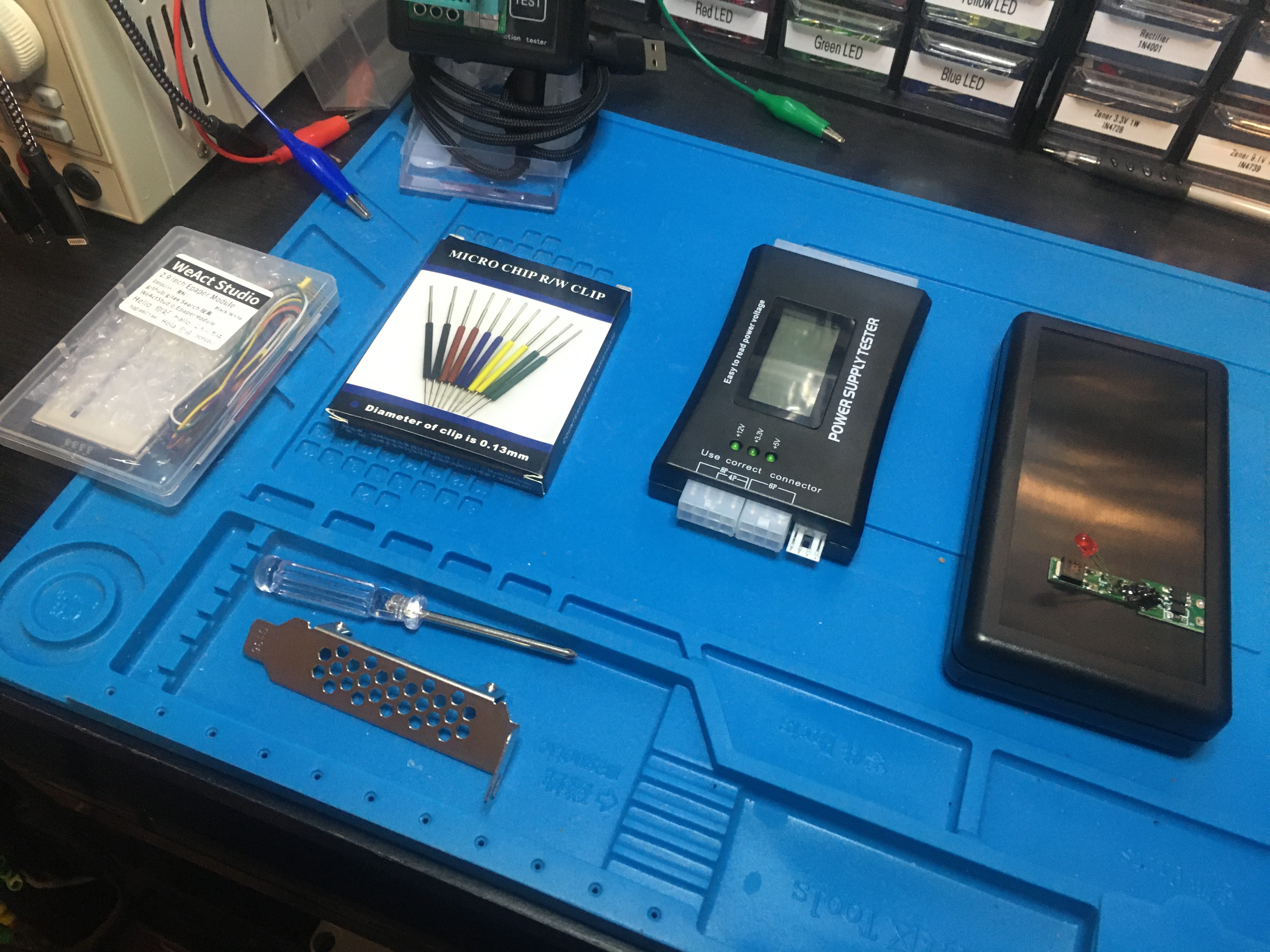
I’ve got some equipment laid out to remind me of four different projects I will be doing soon for In The Lab With Jay Jay.
From left-to-right they are:
I found a bunch of handy information about JST connectors over on Wikipedia: JST connector. There are a bunch of different JST series, it’s worth knowing about these.
I’m off to bed but I thought I should make some notes about what I want to read tomorrow:
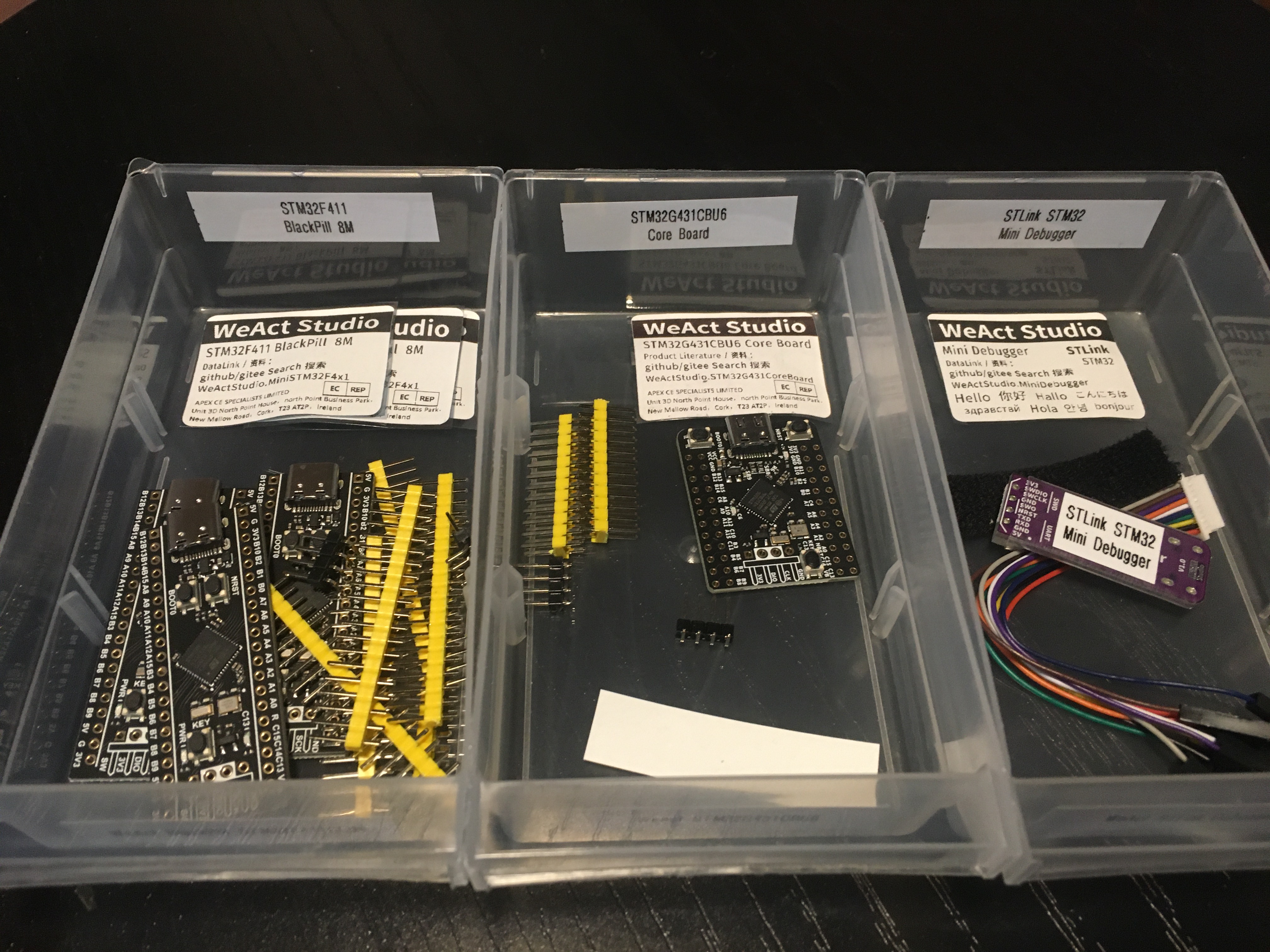
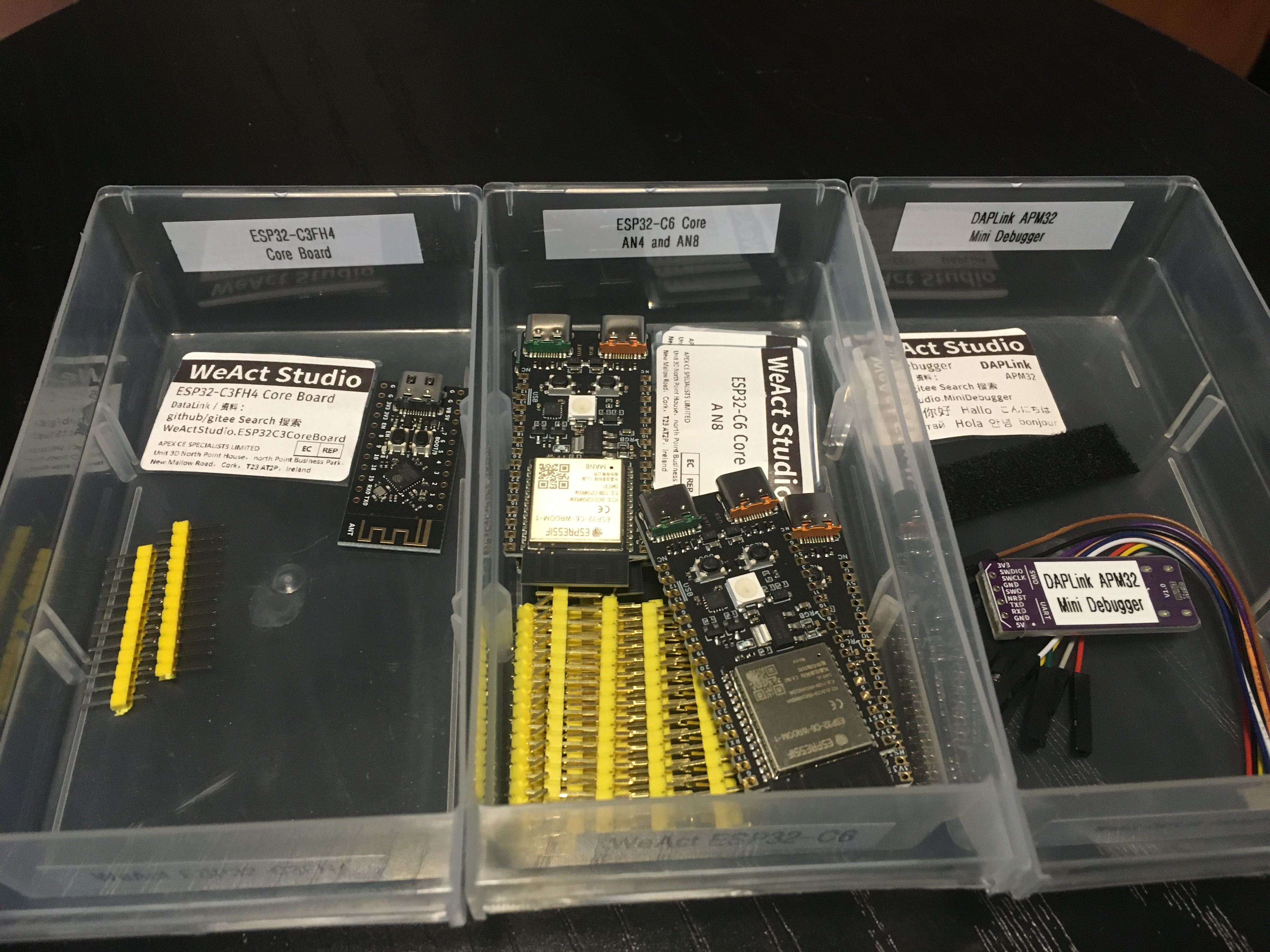
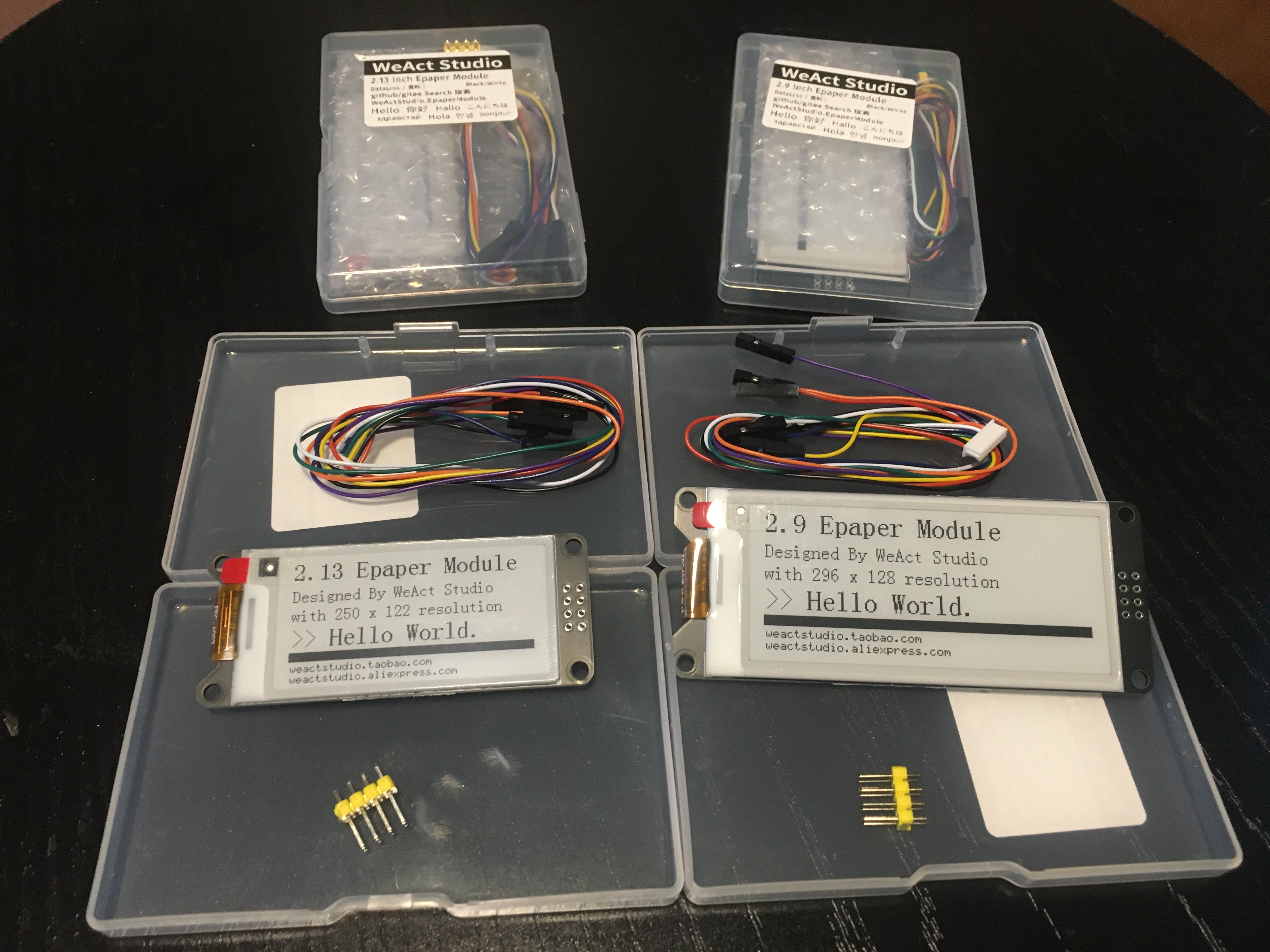
You might remember that last month AliExpress had a sale and I ordered a bunch of stuff. That stuff has started to arrive and I wanted to show you the things I picked up from WeAct Studio.
I don’t know anything about WeAct Studio, I have never heard of them before. But I like what I see so far!
Here’s my WeAct Studio kit which arrived today:
This post is part of my video blog and you can find more information about this video over here.
You can support this channel on Patreon: patreon.com/JohnElliotV
Silly Job Title: Power Provider
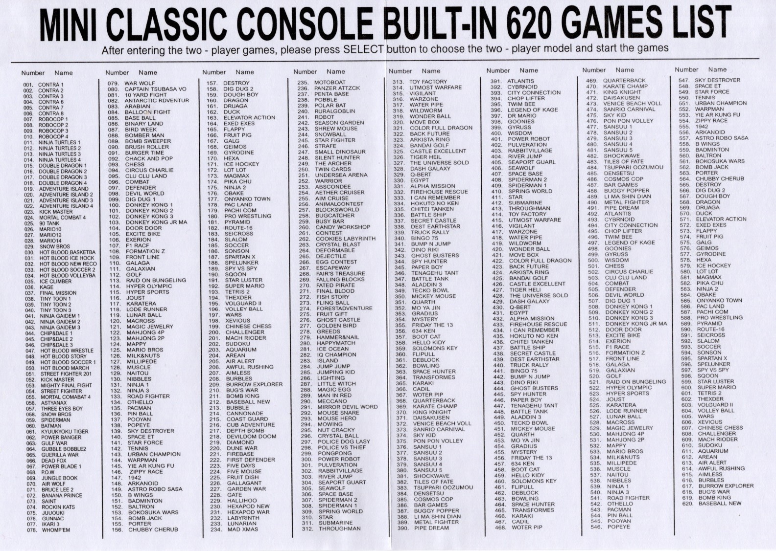
It’s the In The Lab With Jay Jay Halloween Special! This evening: another unboxing video! This time we’re taking a look at my retro gaming console: The Mini Classic Game Console. Complete with 620 odd games!
I picked this thing up at Vinnies (the thrift store) for fifteen Aussie buckaroos.
The main circuit board looks like this:
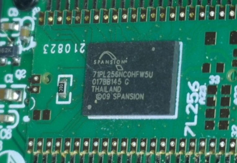
I found the S71PL256NC0HFW5U2 which is a 64Mb flash memory. The details of the other circuitry was obscured.
Here is the list of games on this thing:
And this is the manual:
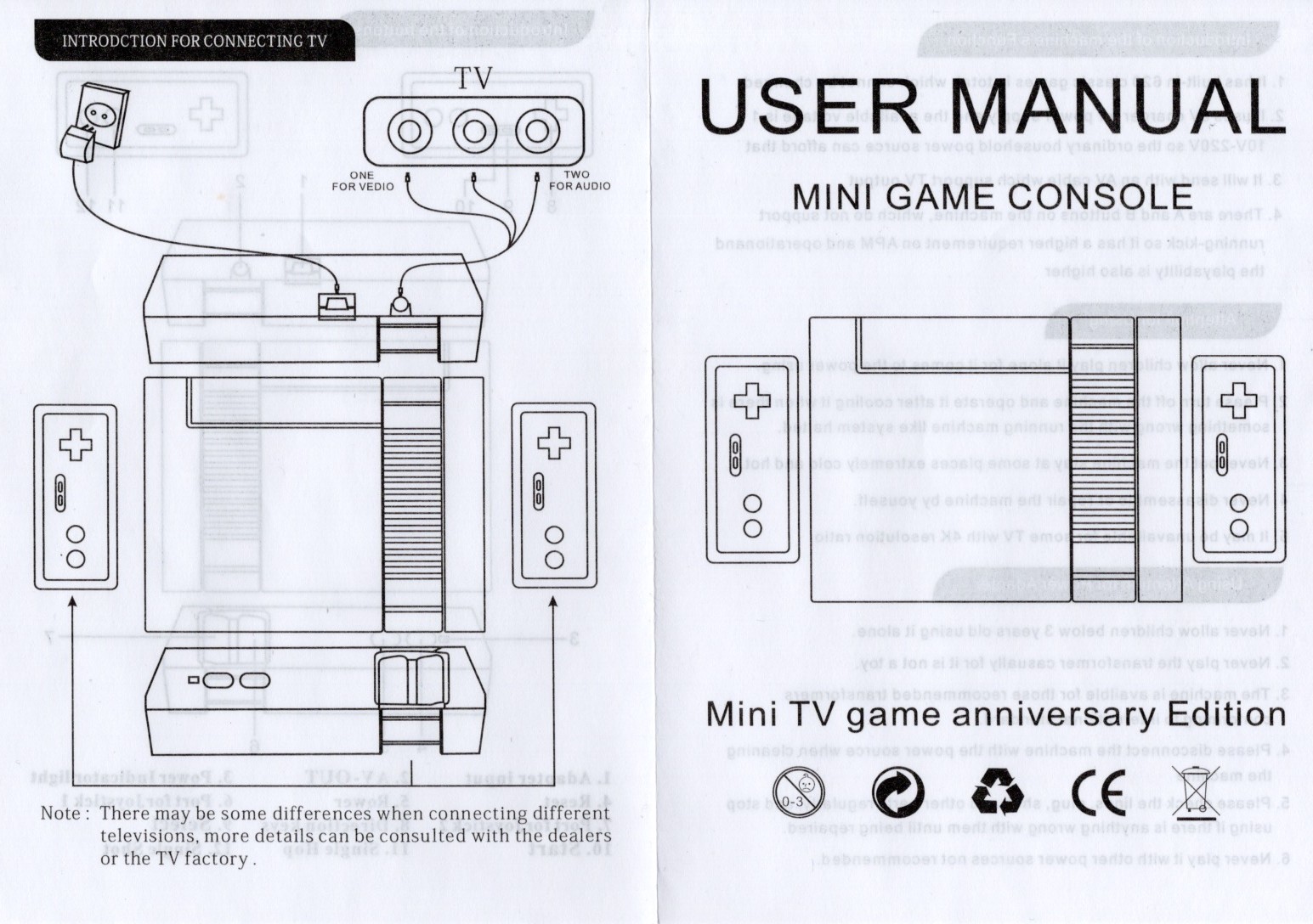
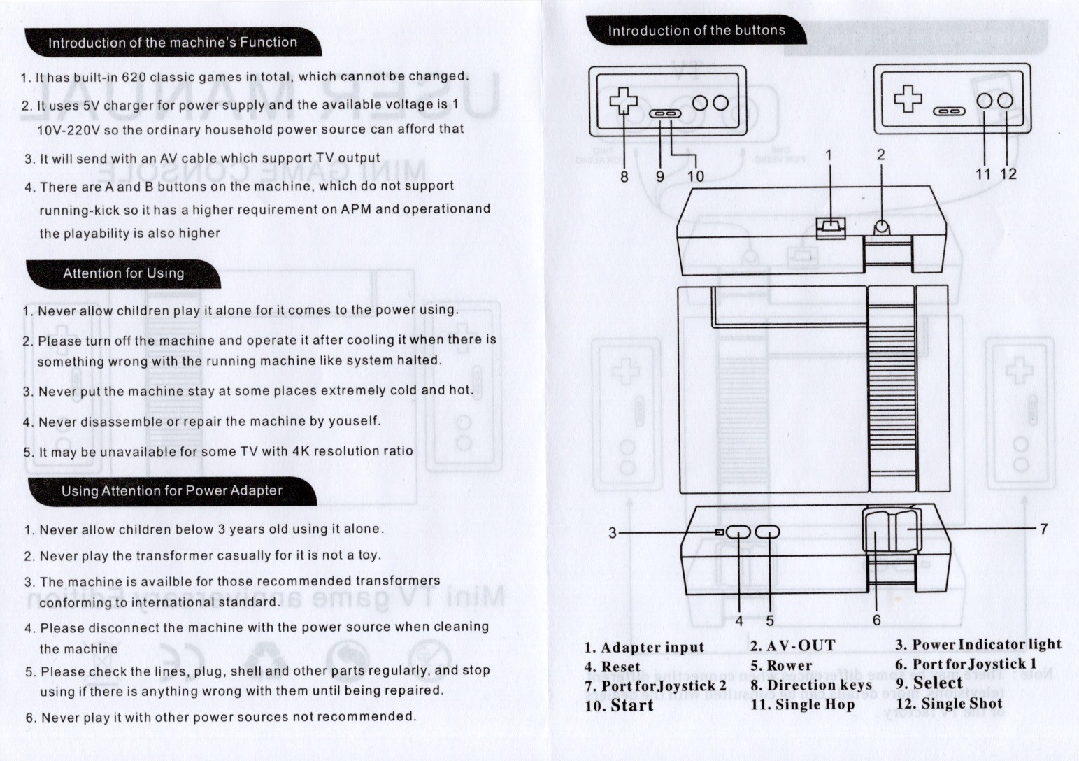
I managed to get this thing wired through an AV to HDMI adapter, then a HDMI to USB adapter, so in the last half of the video you can see me demoing a few of the games and scrolling through the full list of games.
Oh, and in this video I read “NTSL” on the manual and say “they got that wrong, it’s NTSA”, but *I* got that wrong, and it’s “NTSC”. The American video standard. In Australia almost everything is PAL.
Thanks very much for watching! And please remember to hit like and subscribe! :)
Following is a product I use picked at random from my collection which may appear in my videos. Clicking through on this to find and click on the green affiliate links before purchasing from eBay or AliExpress is a great way to support the channel at no cost to you. Thanks!
aToolTour Black Hexagon Deburring Drill Bit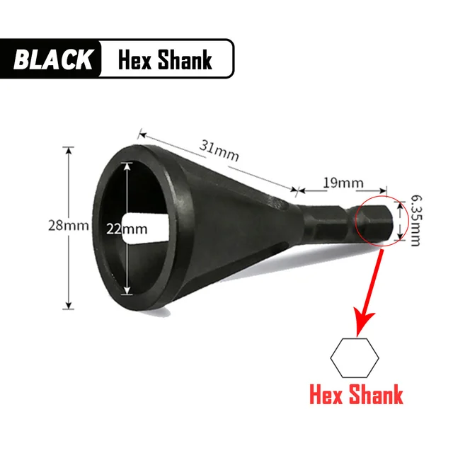 notes notes |
Let’s go shopping!
This post is part of my video blog and you can find more information about this video on this show’s homepage which is here.
You can support this channel on Patreon: patreon.com/JohnElliotV
Silly Job Title: Sparky
Happy Halloween! Today: another unboxing video! This time we’re taking a look at my two new mechanical keyboards from FILCO (affiliate links):
As I mention in the video I usually like to purchase my mechanical keyboards from WASD Keyboards in California. They make excellent keyboards but just a bit too pricey for me at the moment. Instead of purchasing from WASD Keyboards I picked these keyboards up from Amazon Australia and I paid AU$202.55 (US$130) for the 104-key keyboard and AU$188.89 (US$120) for the 87-key keyboard which was roughly half of what I would have had to pay if I purchased from WASD Keyboards.
Both of these FILCO Majestouch 2SS Edition keyboards come with Cherry MX Speed Silver switches. If you’re into mechanical keyboards definitely give these switches a try; now that I’m used to them I will accept nothing less.
It was a bit disappointing that while doing the unboxing I discovered some of the keys had fallen loose during shipping. I have since plugged in and tested the keyboard (I’m using it now in fact) and everything seems to be working okay, so no harm no foul.
Thanks very much for watching! And please remember to hit like and subscribe!
Following is a product I use picked at random from my collection which may appear in my videos. Clicking through on this to find and click on the green affiliate links before purchasing from eBay or AliExpress is a great way to support the channel at no cost to you. Thanks!
Miniware DT71 Digital Tweezers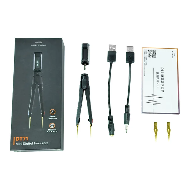 notes notes |
Let’s go shopping!
This post is part of my video blog and you can find more information about this video on this show’s homepage which is here.
You can support this channel on Patreon: patreon.com/JohnElliotV
Silly Job Title: Current Commander
Today: another unboxing video! I do these, not because I think that my regular viewers are going to be particularly interested, but because you really only get the opportunity to do these on the day that new equipment arrives, and I figure it might be helpful for people who search for unboxing videos for a particular product, so they can see what’s in the box before they make a purchasing decision.
This video is an unboxing of two different 4-port HDMI KVM switches. I would give you affiliate links but these don’t seem to be available in the USA, so here are the non-affiliated Amazon Australia links:
For the record I paid AU$64.56 for the AM-KVM401-K (US$40) and AU$84.14 for the KC-KVM401A (US$55). I don’t know what algorithm is in charge of pricing at Amazon but the prices seem to have gone way up since I purchased these things two days ago, now the AM-KVM401-K is AU$75.96 and the KC-KVM401A is AU$98.99, so not sure what’s up with that (but I do NOT like the idea that Amazon has a pricing system that isn’t offering all shoppers the same price all the time, which this smells like).
I reckon the K-CEVE marketing department is going to bit pretty upset with engineering or manufacturing about this, but when I was unboxing the AM-KVM401-K the front panel push button switch just dead set fell out! That’s gotta be embarrassing for someone.
Having done the unboxing I’ve decided I’m gonna try the larger KC-KVM401A unit first. Its larger size is a disadvantage but I like the fact that it has USB-A instead of USB-C inputs and I’m also happy that it has a dedicated 5V power rail, the AM-KVM401-K is powered off the USB bus which is less desirable.
I will post another article later to let you know how I went when I actually plug these things in, which I haven’t actually done yet.
Thanks very much for watching! And please remember to hit like and subscribe!
Following is a product I use picked at random from my collection which may appear in my videos. Clicking through on this to find and click on the green affiliate links before purchasing from eBay or AliExpress is a great way to support the channel at no cost to you. Thanks!
Yum Cha TE-801 Third Hand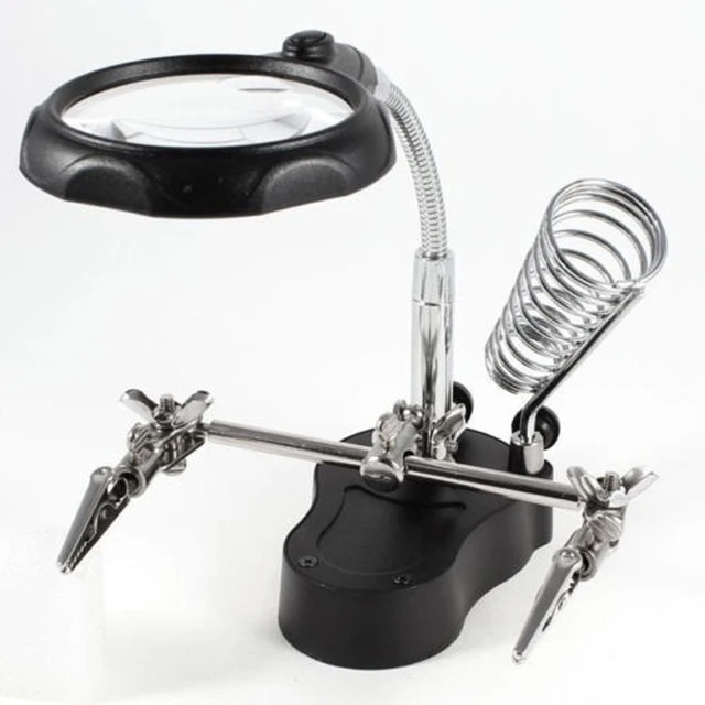 notes notes |
Let’s go shopping!
This post is part of my video blog and you can find more information about this video on this show’s homepage which is here.
You can support this channel on Patreon: patreon.com/JohnElliotV
Silly Job Title: Electron Herder
This video is a teardown of the ALKOY Capacitor Discharge Pen which I did for YouTube user t1d100 who asked me about it over here: Demo of the ALKOY Capacitor Discharge Pen | In The Lab With Jay Jay.
I made a bunch of mistakes while making this video, so please bear with me. I tried to add some captions to explain things when I went wrong.
The discharge pen that I have was purchased from Amazon Australia here: 1000V Portable Capacitor Discharge Pen High Voltage Quick Discharging Tool Constant Discharge Pen Electronic Repairs Discharge Pen ALKOY.
There seems to be a similar product available from Amazon USA here: YEKMLCO Capacitor Discharge Pen Fast Discharging High Voltage 1000V Repair Tool Discharger for Electronic Safety Intelligent (affiliate link).
In the video you can watch me break this thing open. I didn’t exactly know how to do it, and I permanently damaged the device while opening it. In the end I wasn’t 100% sure what the safe and proper way to open these things really is. Giving it a mighty pull might work, otherwise you will need to leverage off some friction locks.
Before I broke the device open I tried to measure the resistance across its probes, but all three measurement devices reported open circuit. The device doesn’t seem to engage the resistor until it detects a voltage.
Eventually I got the device open, you can see some photos of the circuit board below, and I make some attempt to identify the components.
The MB10F on the top is a bridge rectifier, the M7F in the middle is a rectifying diode, and the resistor at the bottom is 2MΩ. In the video I say that the resistor is a “two ohm resistor”, but it is actually a “two MEGA ohm resistor” (I knew that, I just misspoke).
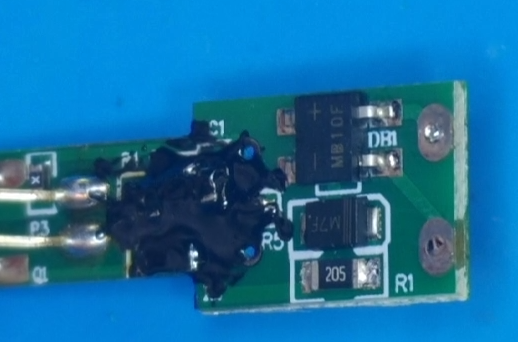
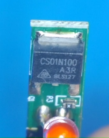
I’m not 100% sure what the CS01N100 A3R is, but it seems than an CS01N100 A4R is a silicon N-Channel Power MOSFET, so I think that’s probably what that is.
As I broke this device during the teardown I have purchased myself a replacement device for AU$23.02.
In the video I use the following equipment (affiliate links where possible):
In the video I have trouble with the connections into the DSO-TC3, the connections are documented here: FNIRSI DSO-TC3.
Thanks very much for watching! And please remember to hit like and subscribe!
Following is a product I use picked at random from my collection which may appear in my videos. Clicking through on this to find and click on the green affiliate links before purchasing from eBay or AliExpress is a great way to support the channel at no cost to you. Thanks!
Yum Cha 52 in 1 Tiger Wrench notes notes |
Let’s go shopping!
Read a bunch of stuff about hardware debugging. Learned a thing or two, but I have much further to go!