Thanks very much for watching! And please remember to hit like and subscribe! :)
Following is a product I use picked at random from my collection which may appear in my videos. Clicking through on this to find and click on the green affiliate links before purchasing from eBay or AliExpress is a great way to support the channel at no cost to you. Thanks!
Thanks very much for watching! And please remember to hit like and subscribe! :)
Following is a product I use picked at random from my collection which may appear in my videos. Clicking through on this to find and click on the green affiliate links before purchasing from eBay or AliExpress is a great way to support the channel at no cost to you. Thanks!
Thanks very much for watching! And please remember to hit like and subscribe! :)
Following is a product I use picked at random from my collection which may appear in my videos. Clicking through on this to find and click on the green affiliate links before purchasing from eBay or AliExpress is a great way to support the channel at no cost to you. Thanks!
We use the UNI-T UTi260B Thermal Imager to examine the thermal characteristics of the circuit, particularly the 1K resistors getting warm.
We use the Riden RD6006 Bench Power Supply to provide 9V for our circuit and also to measure the current drawn by the circuit in its inactive (11mA) and active (12mA) states.
Thanks very much for watching! And please remember to hit like and subscribe! :)
Following is a product I use picked at random from my collection which may appear in my videos. Clicking through on this to find and click on the green affiliate links before purchasing from eBay or AliExpress is a great way to support the channel at no cost to you. Thanks!
We use the UNI-T UTi260B Thermal Imager to watch the thermal effects of the circuit. We see both the 1K resistors in the astable multivibrator get warm, but only the activated side of the bistable multivibrator gets warm.
We use the Riden RD6006 Bench Power Supply to provide 9V for our circuit. I make a mistake and connect it the wrong way around to begin with!
Thanks very much for watching! And please remember to hit like and subscribe! :)
Following is a product I use picked at random from my collection which may appear in my videos. Clicking through on this to find and click on the green affiliate links before purchasing from eBay or AliExpress is a great way to support the channel at no cost to you. Thanks!
We use the Rigol MSO5074 Mixed Signal Oscilloscope to see the output of the astable multivibrator. In the video I make a mistake and attach the probe to the wrong pins.
We use the METCAL PS-900 Soldering Station to solder the wires I use for the banana plugs I attach to the touch sensor an voice sensor (microphone).
We use the UNI-T UTi260B Thermal Imager to look at the heat profile of the circuit. We see that the low resistances (470Ω and 1KΩ) get the warmest, but the higher resistances (e.g. 10KΩ) are also slightly visible.
We use the Peak Electronic Design Atlas LCR45 LCR Meter to measure the resistance of the resistor we use in the LED attachment circuit. This extra circuit allows us to switch out the buzzer for an LED, which makes a lot less racket. The resistor it uses turned out to be 470Ω.
We use the Riden RD6006 Bench Power Supply to provide 9V for our test circuit. Usually I take a current reading to see how much power the circuit draws in its various states, but I forgot!
We use the Horusdy Soldering Station with Hot Air Gun for its hot air gun in order to shrink the heat shrink which we added to the banana plug cables we attached to our sensors.
Thanks very much for watching! And please remember to hit like and subscribe! :)
Following is a product I use picked at random from my collection which may appear in my videos. Clicking through on this to find and click on the green affiliate links before purchasing from eBay or AliExpress is a great way to support the channel at no cost to you. Thanks!
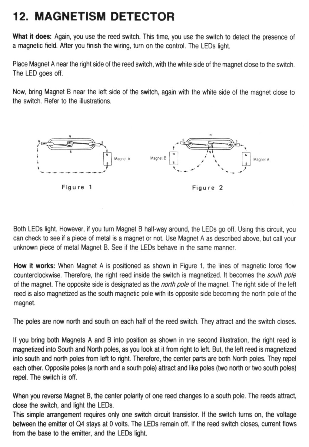
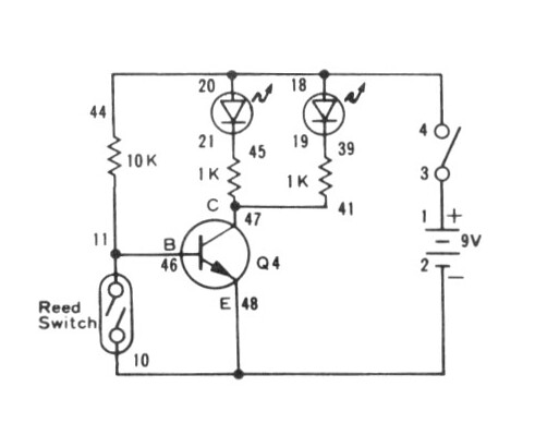
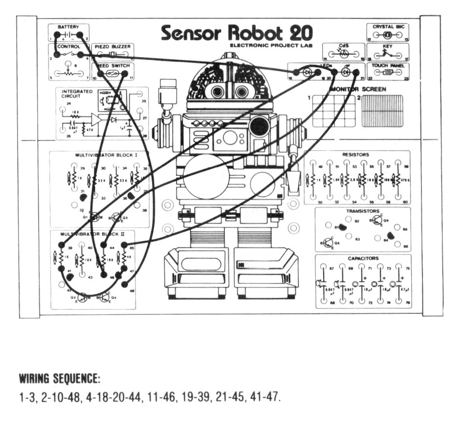
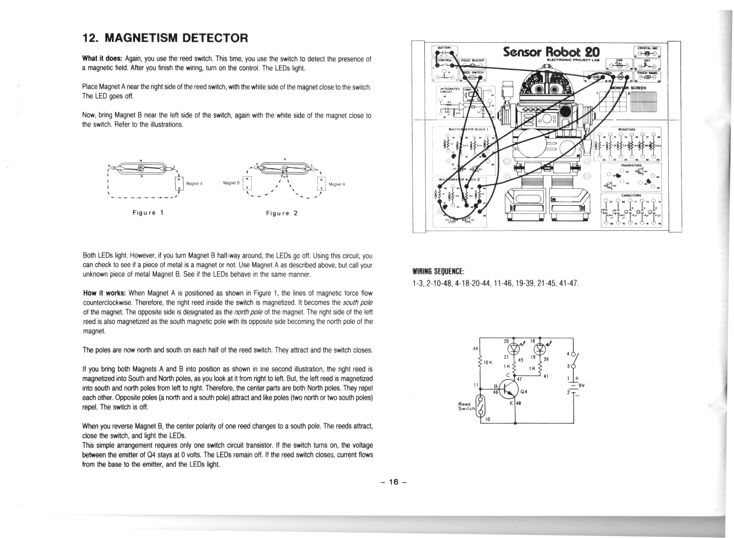
In this video I do the 12th project from the Maxitronix 20in1 (the Sensor Robot 20): Magnetism Detector.
In this project we control a BJT transistor with a magnetic reed switch.
We use the thermal camera to observe heat in the transistors and LEDs during operation.
This is a plain DC circuit with no signals so there was no call for measuring anything with the oscilloscope.
I got myself a little confused about normally open and normally closed circuits during the video, but I think I was clear enough about that in the end.
Thanks very much for watching! And please remember to hit like and subscribe! :)
Following is a product I use picked at random from my collection which may appear in my videos. Clicking through on this to find and click on the green affiliate links before purchasing from eBay or AliExpress is a great way to support the channel at no cost to you. Thanks!
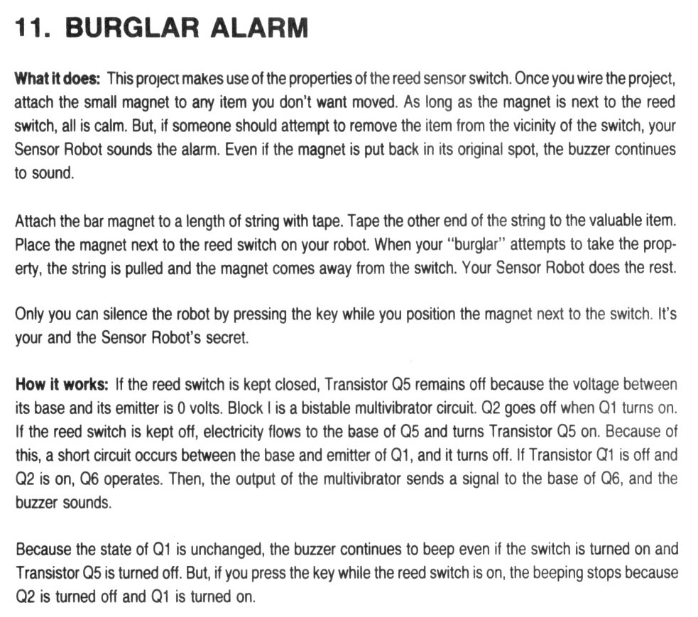
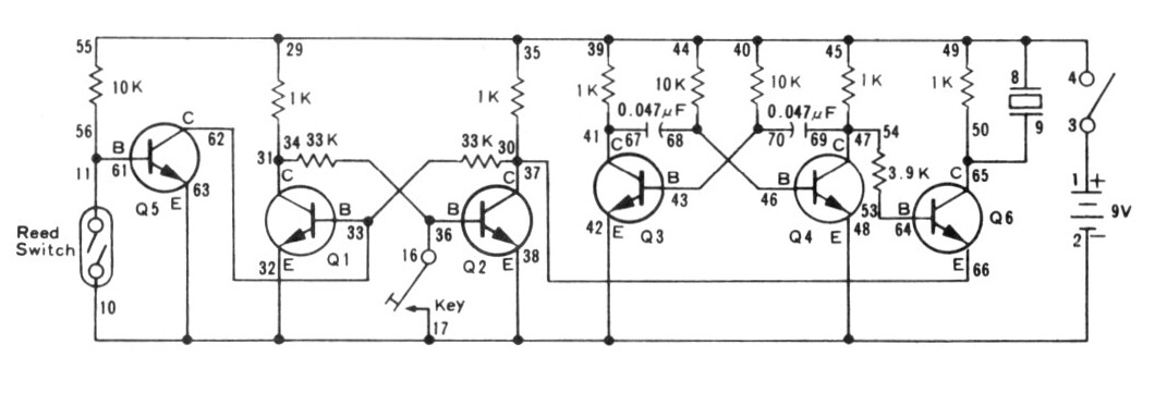
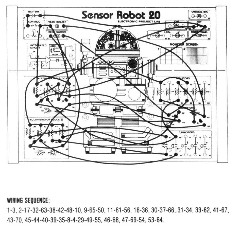
In this video I do the 11th project from the Maxitronix 20in1 (the Sensor Robot 20): Burglar Alarm.
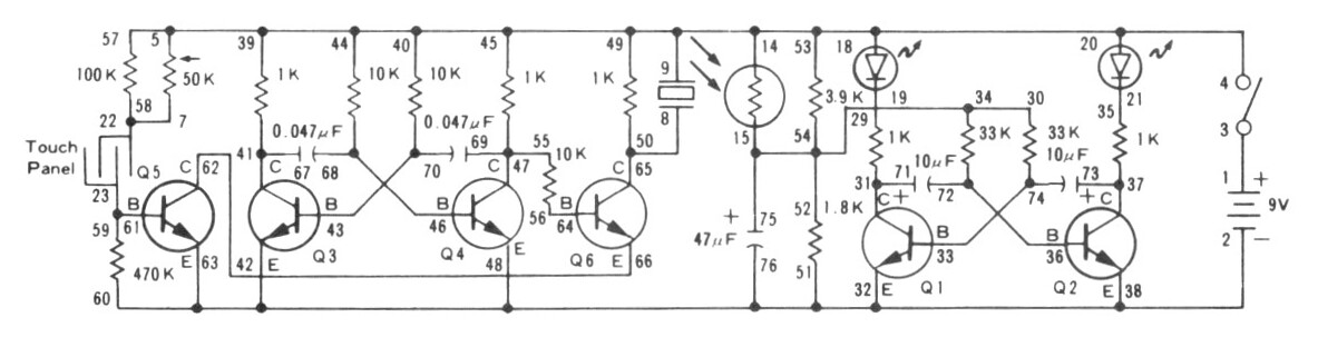
This project uses the reed switch to trigger a bistable multivibrator that controls an alarm. The bistable multivibrator can be reset with the key. An astable multivibrator is used to generate the tone for the audible alarm.
In this project we get some more experience with transistors and how they can be used in various types of multivibrator circuit. Under the thermal camera we can see some of the transistors warming up as they conduct electricity. With the oscilloscope we can see the periodic waveform used to generate the alarm tone.
Thanks very much for watching! And please remember to hit like and subscribe! :)
Following is a product I use picked at random from my collection which may appear in my videos. Clicking through on this to find and click on the green affiliate links before purchasing from eBay or AliExpress is a great way to support the channel at no cost to you. Thanks!
Today I learned about the Baker clamp. It’s a circuit to help speed up transistor switching time. I learned about it over on Diode-transistor logic § Speed improvement where it said it was developed by Richard H. Baker who described it in his 1956 technical report.