Rain Detector | Project 18/20 | Maxitronix 20in1 | Learning Electronics In The Lab With Jay Jay

This post is part of my video blog and you can find more information about this video over here.

You can support this channel on Patreon: patreon.com/JohnElliotV

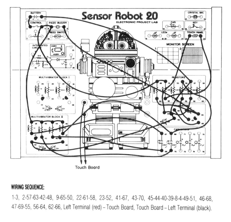
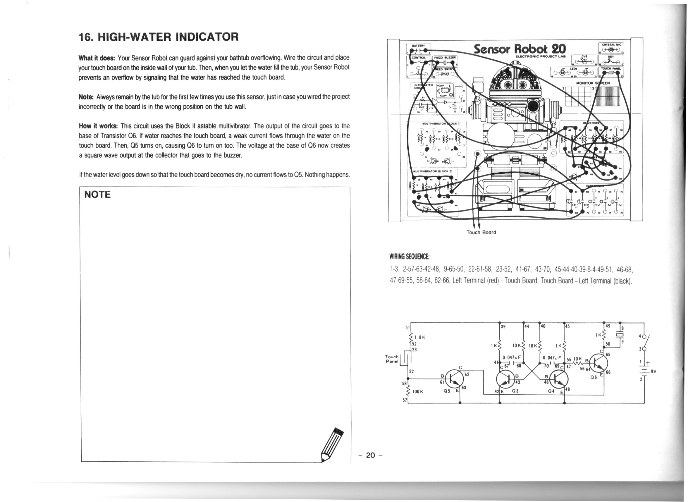
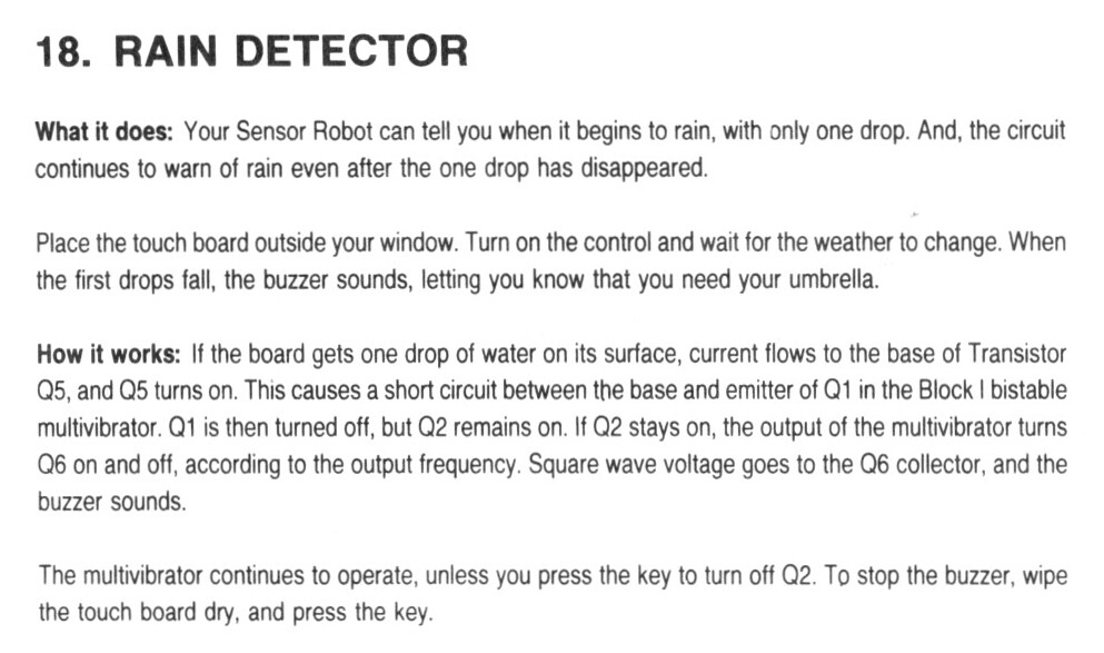
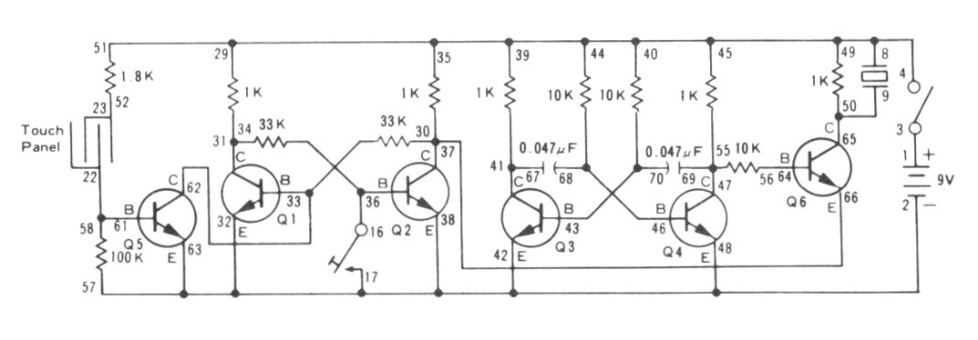
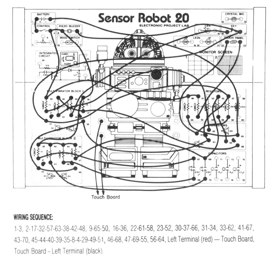
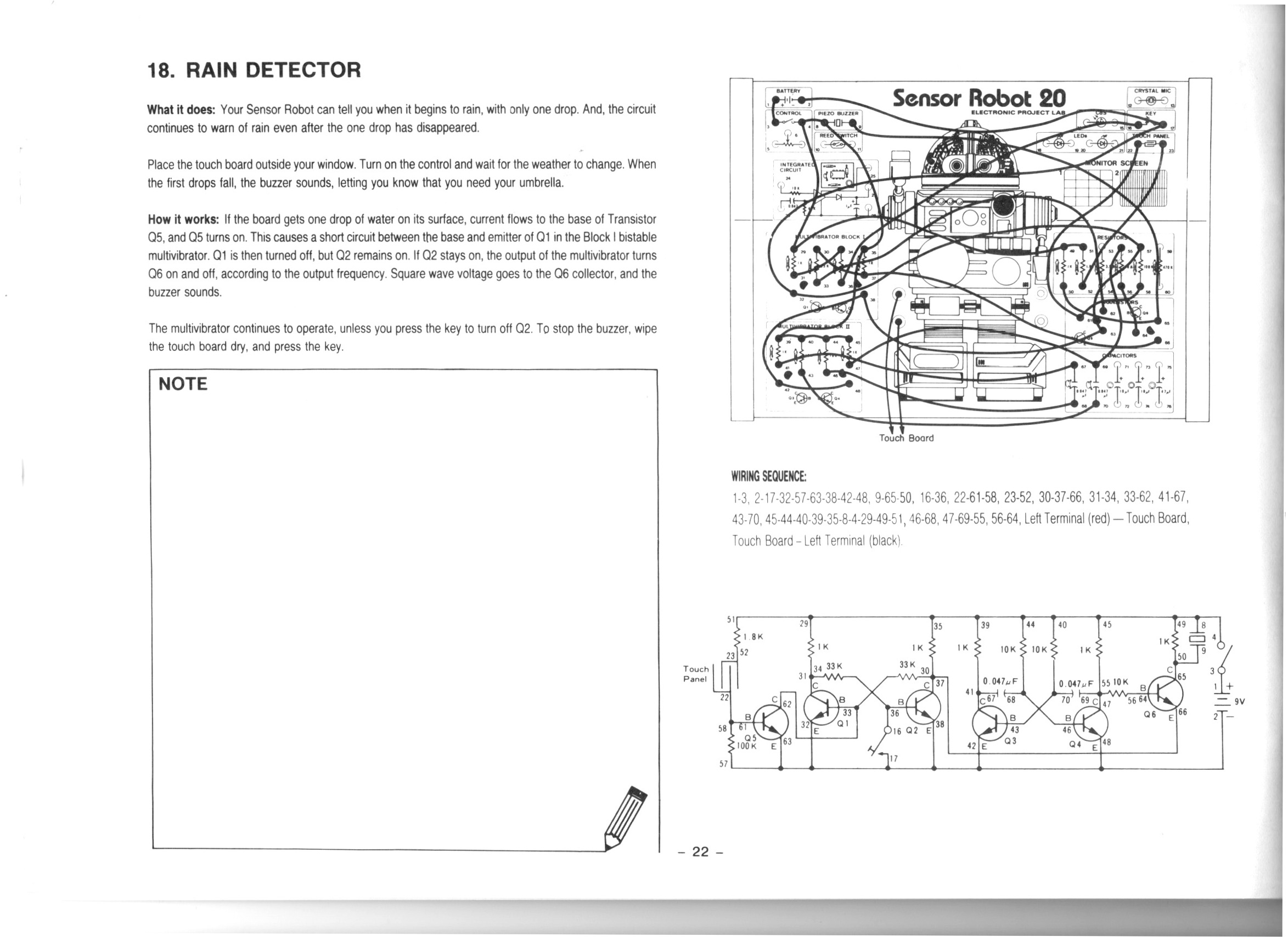
In this video we do the 18th project from the Maxitronix Sensor Robot 20 (20in1) Electronics Project Lab Kit: Rain Detector.

We use the Rigol MSO5074 Mixed Signal Oscilloscope to see the 1.6 kHz square wave from our astable multivibrator.

We use the UNI-T UTi260B Thermal Imager to watch the thermal effects of the circuit. We see both the 1K resistors in the astable multivibrator get warm, but only the activated side of the bistable multivibrator gets warm.

We use the Fluke 17B+ Digital Multimeter to buzz out the circuit looking for mistakes.

We use the Riden RD6006 Bench Power Supply to provide 9V for our circuit. I make a mistake and connect it the wrong way around to begin with!

Thanks very much for watching! And please remember to hit like and subscribe! :)


Following is a product I use picked at random from my collection which may appear in my videos. Clicking through on this to find and click on the green affiliate links before purchasing from eBay or AliExpress is a great way to support the channel at no cost to you. Thanks!

TOOKKS HZY ABS Wire FixtureThis is an image of the product.notes

Let’s go shopping!

Low-Water Indicator | Project 17/20 | Maxitronix 20in1 | In The Lab With Jay Jay

This post is part of my video blog and you can find more information about this video over here.

You can support this channel on Patreon: patreon.com/JohnElliotV

In this video we do the 17th project from the Maxitronix Sensor Robot 20 (20in1) Electronics Project Lab Kit: Low-Water Indicator.

We use the Rigol MSO5074 Mixed Signal Oscilloscope to see the output of the astable multivibrator. In the video I make a mistake and attach the probe to the wrong pins.

We use the METCAL PS-900 Soldering Station to solder the wires I use for the banana plugs I attach to the touch sensor an voice sensor (microphone).

We use the UNI-T UTi260B Thermal Imager to look at the heat profile of the circuit. We see that the low resistances (470Ω and 1KΩ) get the warmest, but the higher resistances (e.g. 10KΩ) are also slightly visible.

We use the Fluke 17B+ Digital Multimeter to check the resistance of the touch sensor.

We use the Peak Electronic Design Atlas LCR45 LCR Meter to measure the resistance of the resistor we use in the LED attachment circuit. This extra circuit allows us to switch out the buzzer for an LED, which makes a lot less racket. The resistor it uses turned out to be 470Ω.

We use the Riden RD6006 Bench Power Supply to provide 9V for our test circuit. Usually I take a current reading to see how much power the circuit draws in its various states, but I forgot!

We use the Horusdy Soldering Station with Hot Air Gun for its hot air gun in order to shrink the heat shrink which we added to the banana plug cables we attached to our sensors.

Thanks very much for watching! And please remember to hit like and subscribe! :)


Following is a product I use picked at random from my collection which may appear in my videos. Clicking through on this to find and click on the green affiliate links before purchasing from eBay or AliExpress is a great way to support the channel at no cost to you. Thanks!

Yum Cha 9-Inch Needle Nose PliersThis is an image of the product.notes

Let’s go shopping!

High-Water Indicator | Project 16/20 | Maxitronix 20in1 | In The Lab With Jay Jay

This post is part of my video blog and you can find more information about this video over here.

You can support this channel on Patreon: patreon.com/JohnElliotV

In this video we do the 16th project from the Maxitronix Sensor Robot 20 (20in1) Electronics Project Lab Kit: High-Water Indicator.

After we build the circuit we dump the sensor in a glass of water which causes the alarm to trigger. To avoid the obnoxious noise we put an LED in place of the buzzer.

Please be aware: while talking about this circuit I said that the astable multivibrator “flip flops” between states. And that’s kind of true in one sense, but I should be clear than an astable multivibrator is not a “flip flop” circuit. A flip flop circuit is a different type of circuit known as a bistable multivibrator, which is a different kind of thing. In this experiment we use an astable multivibrator to generate a 1.62 kHz square wave which provides our tone, we do not use a flip flop or bistable multivibrator circuit.

We use the Rigol MSO5074 Mixed Signal Oscilloscope to measure and visualize the 1.62 kHz square wave which generates our tone.

We use the UNI-T UTi260B Thermal Imager to investigate the circuit thermals. We see that the 1K resistors in the astable multivibrator generate the most heat.

We use the Fluke 17B+ Digital Multimeter to measure the voltage across Q5. Between about 500 mV and 750 mV is enough voltage to enable the output.

We use the Riden RD6006 Bench Power Supply to deliver the 9V DC required for the project. We use the current measurement from the power supply to see that when the LED is active the circuit draws about 23 mA compared to about 11 mA when the LED is not active.

We use the Horusdy Soldering Station with Hot Air Gun to dry the sensor after it got wet.

Thanks very much for watching! And please remember to hit like and subscribe! :)


Following is a product I use picked at random from my collection which may appear in my videos. Clicking through on this to find and click on the green affiliate links before purchasing from eBay or AliExpress is a great way to support the channel at no cost to you. Thanks!

Ausum 25 In 1 Precision Screwdriver SetThis is an image of the product.notes

Let’s go shopping!

Mail Call #10: Thanks Craig! Also loot from AliExpress | In The Lab With Jay Jay

This post is part of my video blog and you can find more information about this video over here.

You can support this channel on Patreon: patreon.com/JohnElliotV

In this video I receive Engineer’s Mini Notebook Volume II – Science and Communication Circuits & Projects all the way from the USA from my friend (and mentor (and reader (and viewer (and patron (and Lisp hacker))))) Craig. Thanks Craig! <3

I mention that the October 2024 edition of Silicon Chip magazine is out.

I mention that I recently got my symbol keyboard working on Linux! Pretty happy about that! These are the extra keys that I have at my workstation now: ° ± § λ Δ Σ Π Ω ε µ π θ

I also get a bunch of stuff from AliExpress, including:

And yes, despite confusion, I did get three lots of two different kinds of hard brushes, and yes, I did end up saying the wrong thing in the video! Can’t take me anywhere.

Oh, and as I mention in the video I am from a beautiful part of the world known as the Blue Mountains. It’s pretty hot here today!

In the end my collection of Arduino boards includes:

Thanks very much for watching! And please remember to hit like and subscribe! :)


Following is a product I use picked at random from my collection which may appear in my videos. Clicking through on this to find and click on the green affiliate links before purchasing from eBay or AliExpress is a great way to support the channel at no cost to you. Thanks!

Wozniak Solder LugsThis is an image of the product.notes

Let’s go shopping!

Fluke VoltAlert

I was watching this old EEVBlog video: EEVblog #168 – How To Set Up An Electronics Lab and Dave recommended a Fluke VoltAlert. I discovered there are various versions, such as the 1AC and 2AC, and those alternatives are explained here: Best Non-Contact Voltage Tester.

The Fluke 1AC II Non-Contact Voltage Tester looked like a pretty good one for my purposes and I found one on eBay for AUD$35.40 so I hit the buy button.