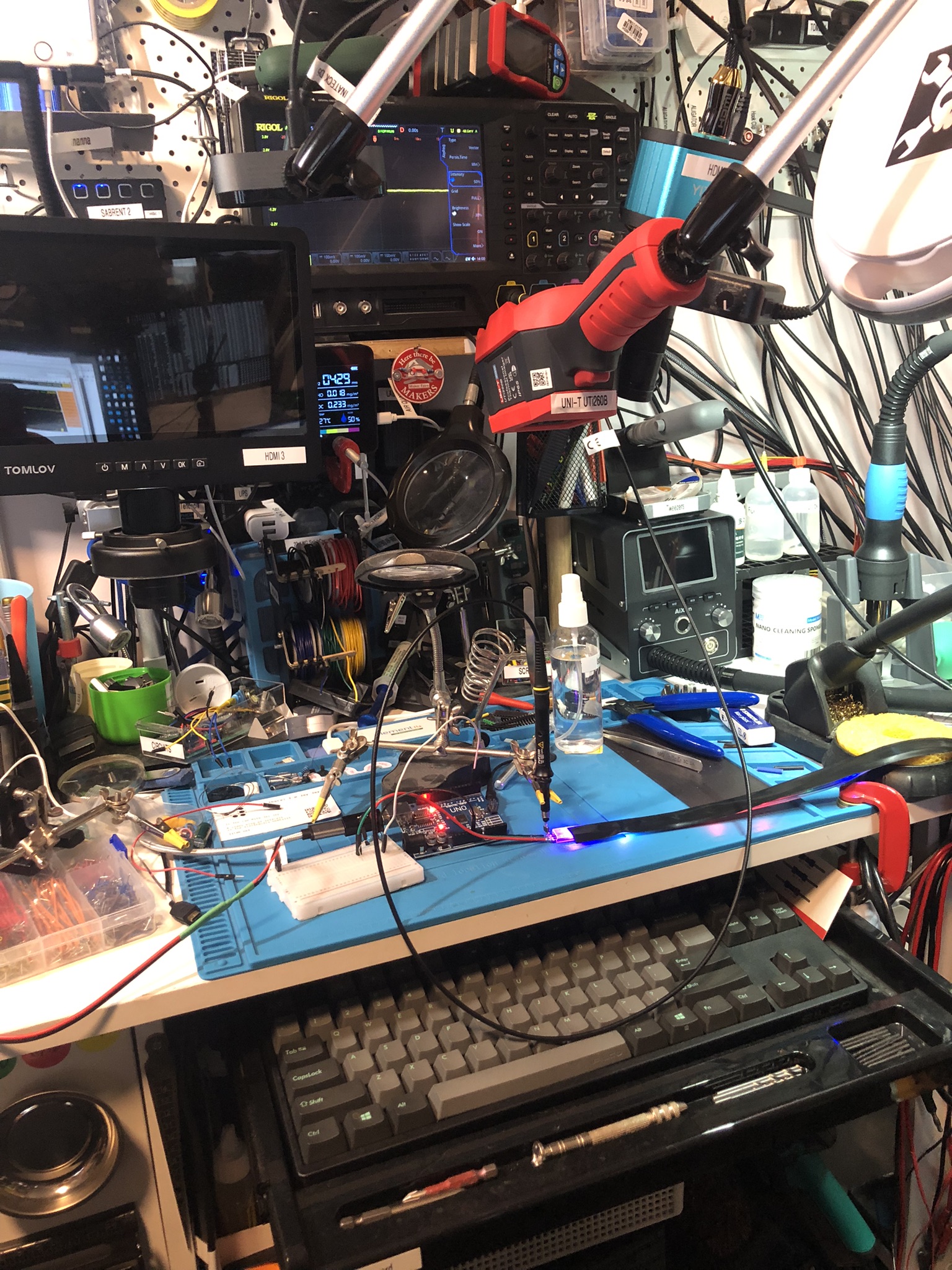
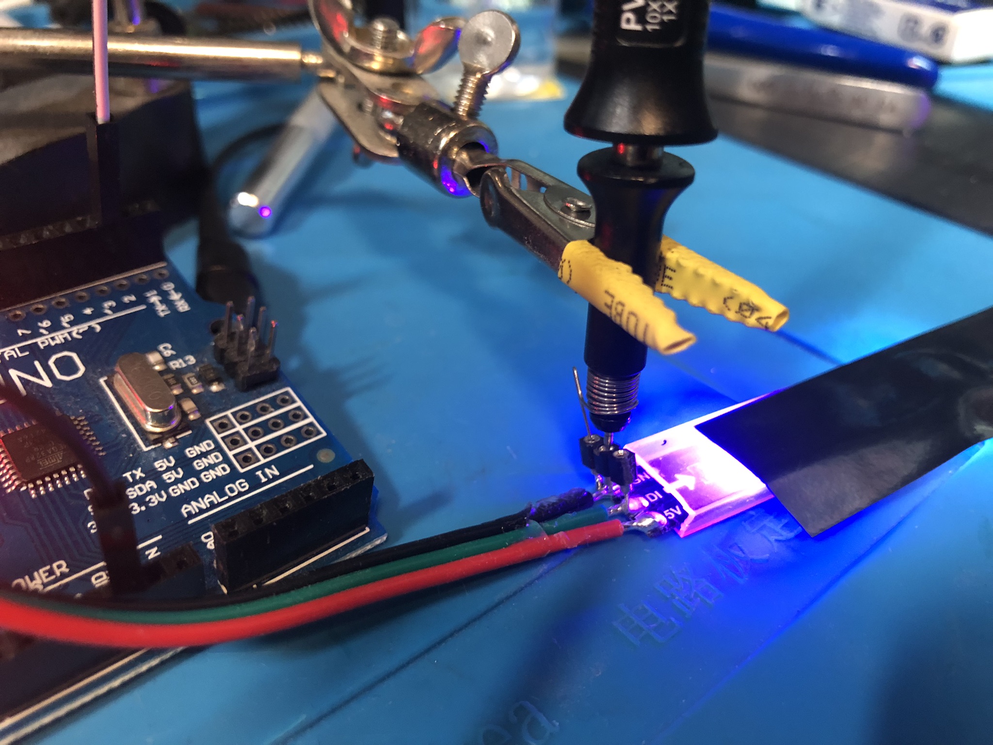
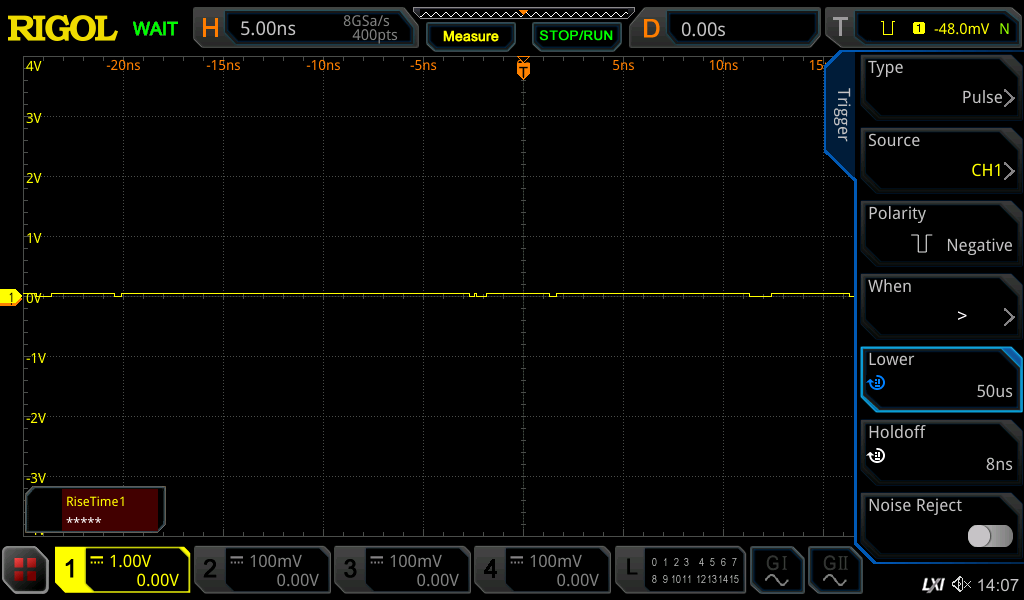
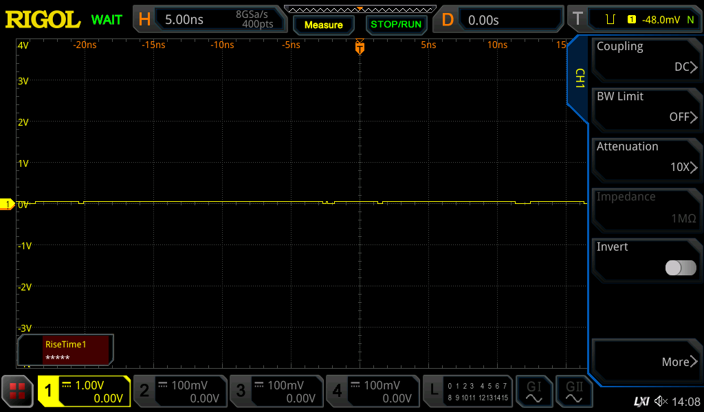
Oh man. Everything’s broken and I don’t know what I’m doing. I have a NeoPixel LED strip which isn’t working right. I’m trying to debug the issue but am not having a good time of it.
Tag Archives: MSO5074
The Electronic Storage Tank | Project 2/30 | Maxitronix 30in1 | In The Lab With Jay Jay
This post is part of my video blog and you can find more information about this video.
You can support this channel on Patreon: patreon.com/JohnElliotV
Silly Job Title: Tech Lead. I am the Tech Lead!
In this video we do the 2nd project from the Maxitronix 30in1 Electronics Project Lab Kit: The Electronic Storage Tank.
We use the Rigol MSO5074 Mixed Signal Oscilloscope to measure the voltage across the capacitor.
We use the UNI-T UTi260B Thermal Imager to check for thermal response (there was none).
We use the Riden RD6006 Bench Power Supply to provide 3V to our test circuit.
We use the EEVblog BM2257 Digital Multimeter to measure voltage across the capacitor.
We use the Peak Electronic Design Atlas DCA75 Pro Semiconductor Analyzer to measure the forward voltage of our LED.
We use the Kaisi S-160 45x30cm Repair Mat as our workspace.
Thanks very much for watching! And please remember to hit like and subscribe! :)
Following is a product I use picked at random from my collection which may appear in my videos. Clicking through on this to find and click on the green affiliate links before purchasing from eBay or AliExpress is a great way to support the channel at no cost to you. Thanks!
Rigol PLA2216 Compatible Logic Probe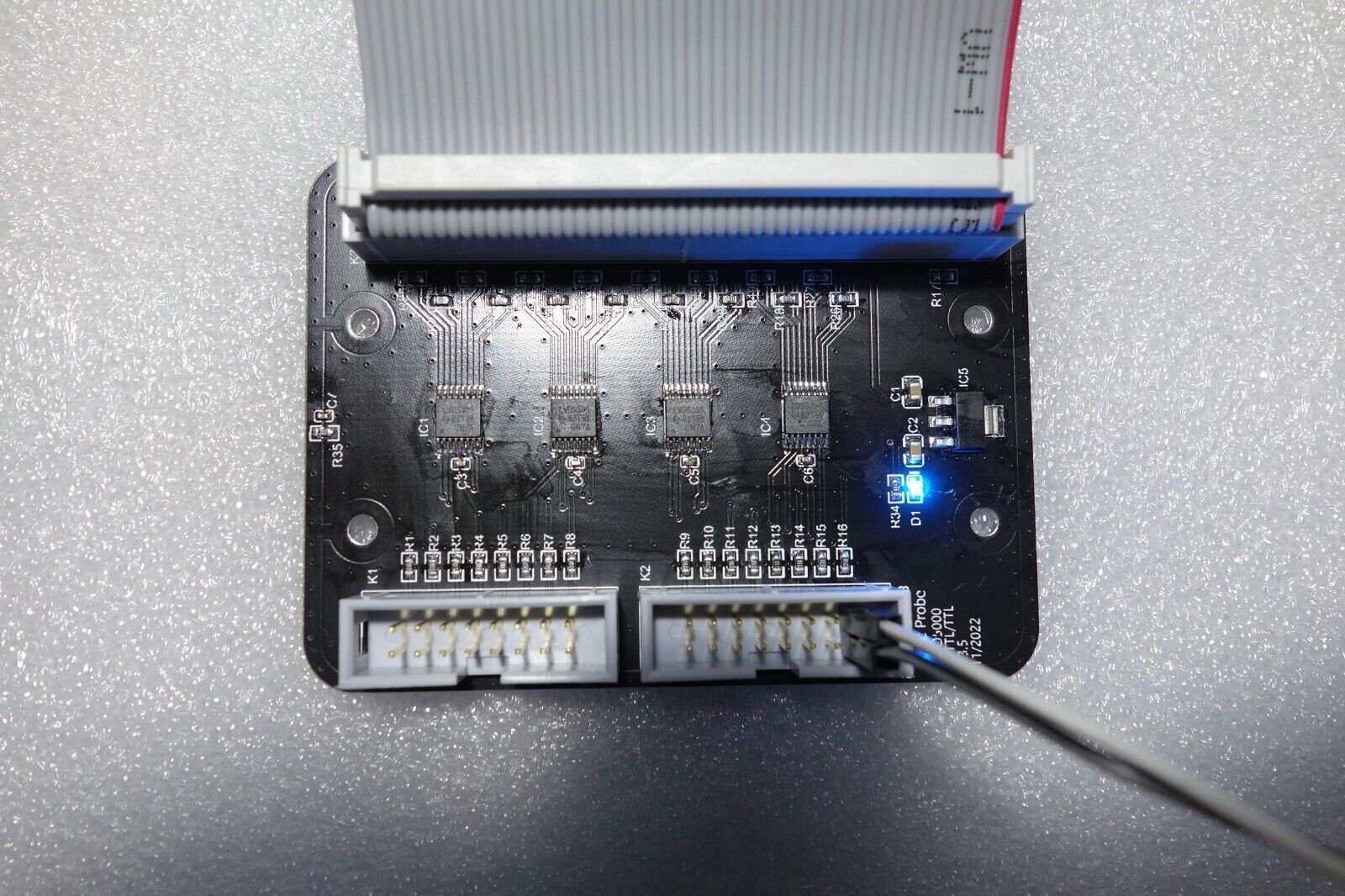 notes notes |
Let’s go shopping!
Intro Project | Project 1/30 | Maxitronix 30in1 | Learning Electronics In The Lab With Jay Jay
This post is part of my video blog and you can find more information about this video over here.
You can support this channel on Patreon: patreon.com/JohnElliotV
Silly Job Title: Relay Renegade.
In this video we build project #1 of our Maxitronix 30in1, the Intro Project.
We use the Rigol MSO5074 Mixed Signal Oscilloscope to examine our circuit.
We use the UNI-T UTi260B Thermal Imager to examine the thermals.
We use the EEVblog BM2257 Digital Multimeter to test continuity and measure current and resistance.
We use the Peak Electronic Design Atlas LCR45 LCR Meter to get vital statistics for our transformer and piezo earphone.
We use the Riden RD6006 Bench Power Supply to power our test circuit.
We use the Horusdy Soldering Station with Hot Air Gun to shrink our heat shrink.
We use the Scotch Titanium Scissors to cut our heat shrink.
We use the Plato Model 170 Wire Cutter to cut wire.
Thanks very much for watching! And please remember to hit like and subscribe! :)
Following is a product I use picked at random from my collection which may appear in my videos. Clicking through on this to find and click on the green affiliate links before purchasing from eBay or AliExpress is a great way to support the channel at no cost to you. Thanks!
Yum Cha 10pc File & Rasp Set Metal File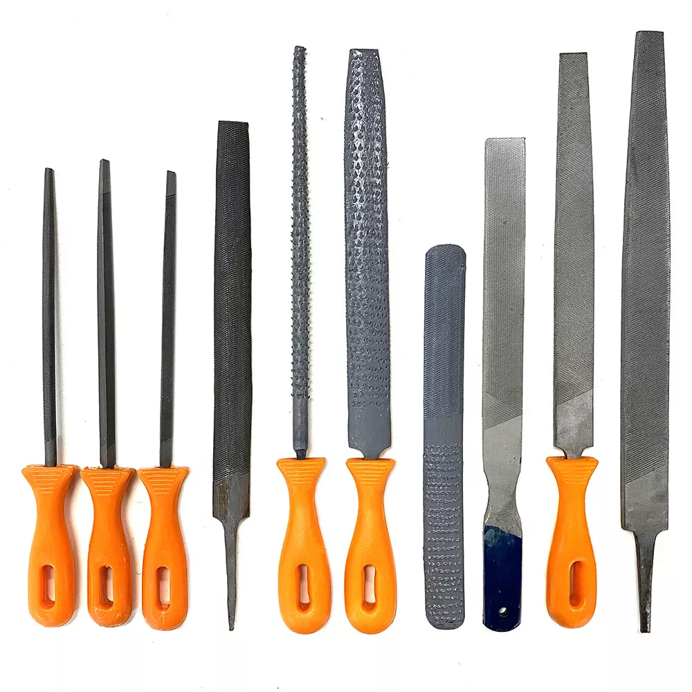 |
Let’s go shopping!
Weather Indicator | Project 20/20 | Maxitronix 20in1 | Learning Electronics In The Lab With Jay Jay
This post is part of my video blog and you can find more information about this video over here.
You can support this channel on Patreon: patreon.com/JohnElliotV
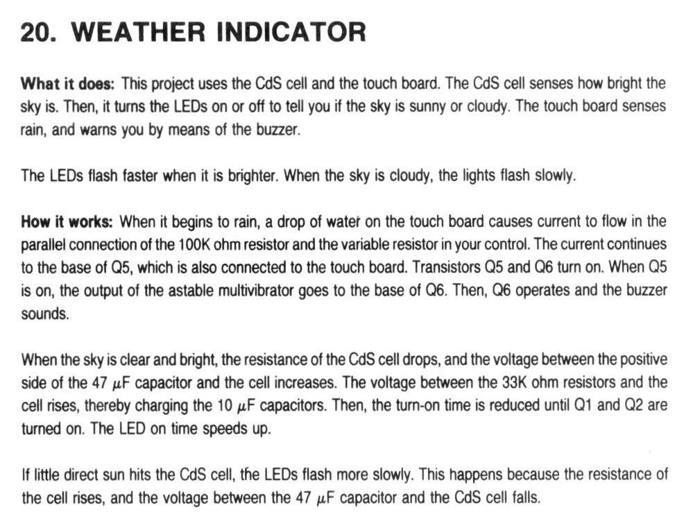
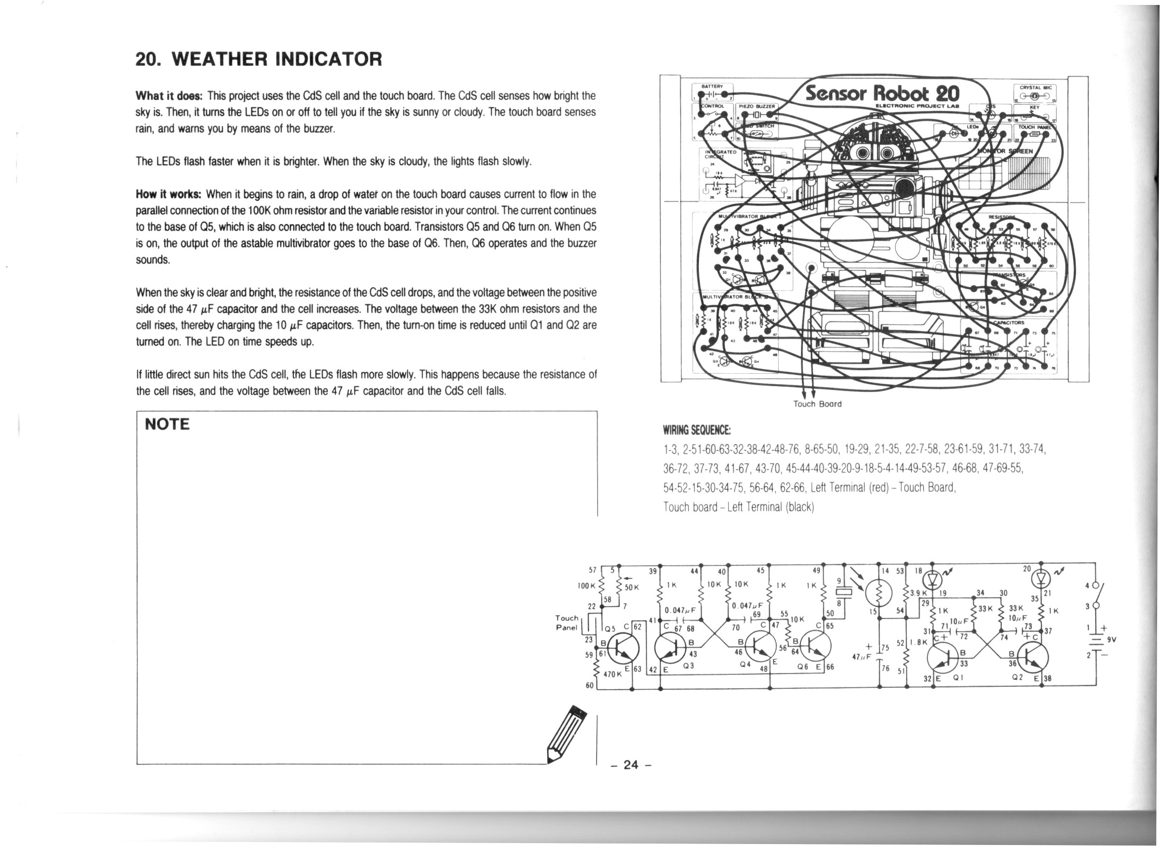
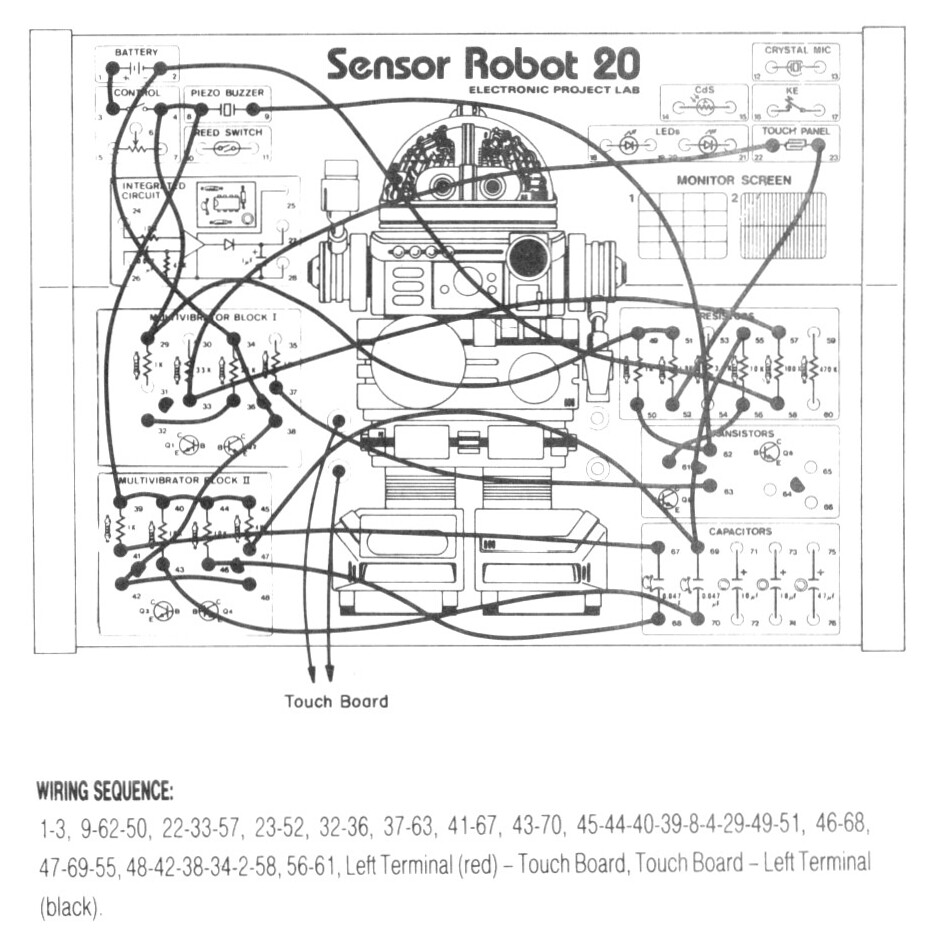
In this video we do the 20th project from the Maxitronix Sensor Robot 20 (20in1) Electronics Project Lab Kit: Weather Indicator.
We use the Rigol MSO5074 Mixed Signal Oscilloscope to have a look at the two square waves from the astable multivibrators.
We use the UNI-T UTi260B Thermal Imager to investigate the circuit’s heat profile.
We use the Riden RD6006 Bench Power Supply to deliver 9V to power the circuit and to report on its current draw.
Thanks very much for watching! And please remember to hit like and subscribe! :)
Following is a product I use picked at random from my collection which may appear in my videos. Clicking through on this to find and click on the green affiliate links before purchasing from eBay or AliExpress is a great way to support the channel at no cost to you. Thanks!
Yum Cha Macro Programmable 8-Key Mechanical Keyboard |
Let’s go shopping!
Touch Buzzer | Project 19/20 | Maxitronix 20in1 | Learning Electronics In The Lab With Jay Jay
This post is part of my video blog and you can find more information about this video over here.
You can support this channel on Patreon: patreon.com/JohnElliotV
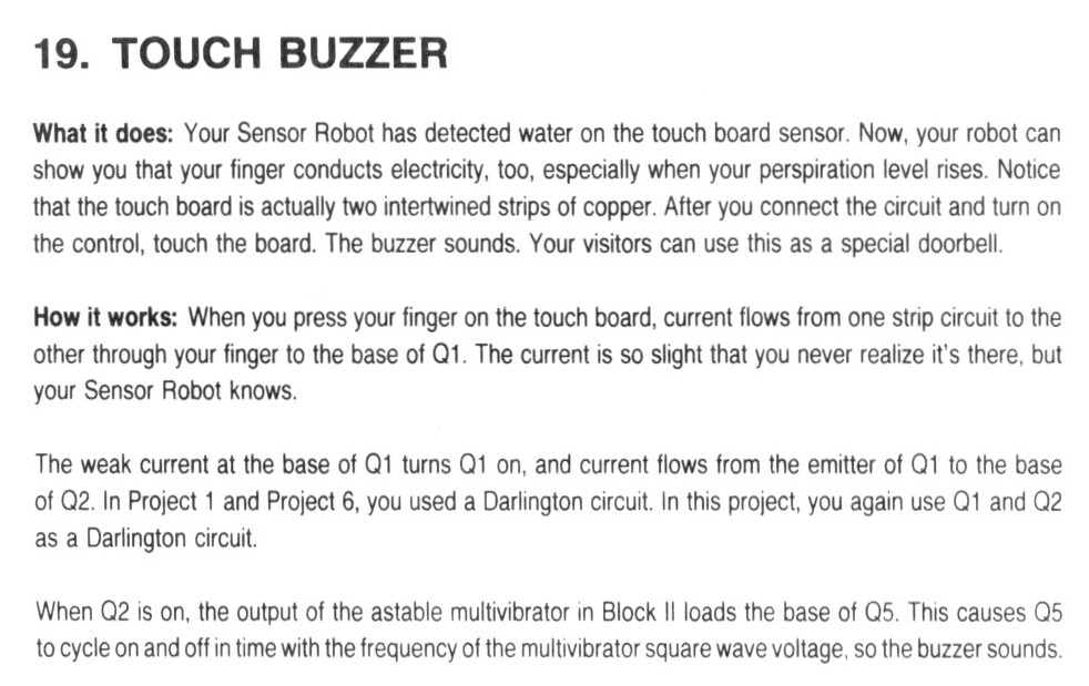
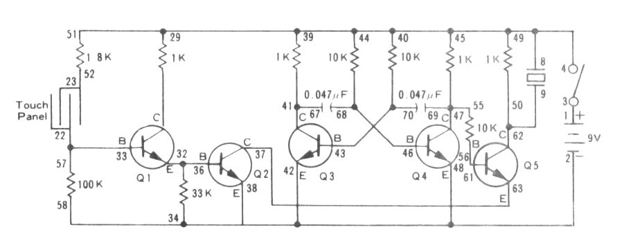
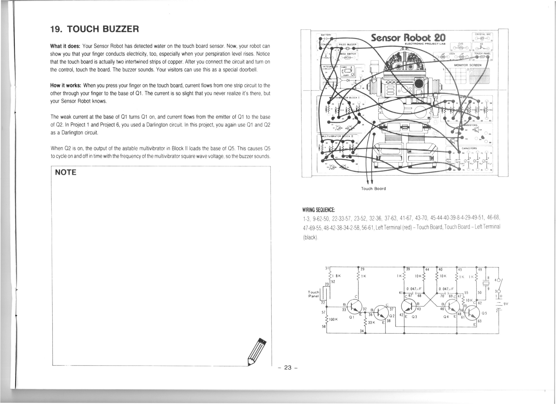
In this video we do the 19th project from the Maxitronix Sensor Robot 20 (20in1) Electronics Project Lab Kit: Touch Buzzer.
This circuit uses a Darlington pair to amplify the very weak signal from the touch sensor.
We use the Rigol MSO5074 Mixed Signal Oscilloscope to look at the square wave from the astable multivibrator.
We use the UNI-T UTi260B Thermal Imager to examine the thermal characteristics of the circuit, particularly the 1K resistors getting warm.
We use the Riden RD6006 Bench Power Supply to provide 9V for our circuit and also to measure the current drawn by the circuit in its inactive (11mA) and active (12mA) states.
Thanks very much for watching! And please remember to hit like and subscribe! :)
Following is a product I use picked at random from my collection which may appear in my videos. Clicking through on this to find and click on the green affiliate links before purchasing from eBay or AliExpress is a great way to support the channel at no cost to you. Thanks!
Maxitronix 500in1 Electronics Project Lab Kit notes notes |
Let’s go shopping!
Rain Detector | Project 18/20 | Maxitronix 20in1 | Learning Electronics In The Lab With Jay Jay
This post is part of my video blog and you can find more information about this video over here.
You can support this channel on Patreon: patreon.com/JohnElliotV
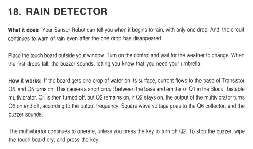
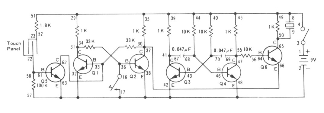
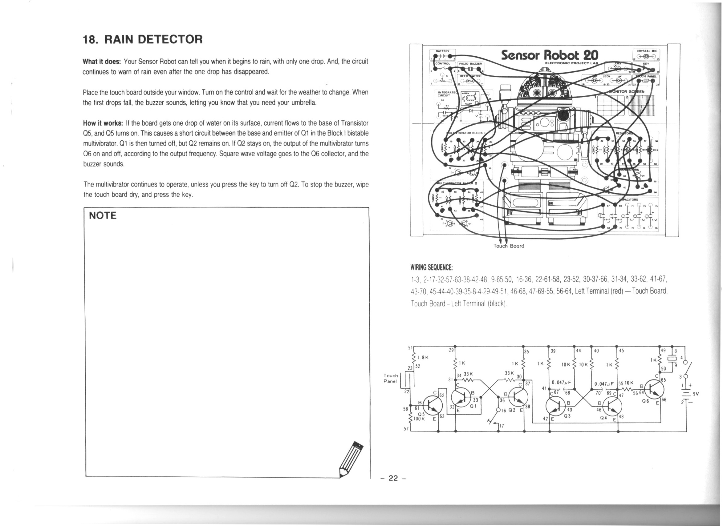
In this video we do the 18th project from the Maxitronix Sensor Robot 20 (20in1) Electronics Project Lab Kit: Rain Detector.
We use the Rigol MSO5074 Mixed Signal Oscilloscope to see the 1.6 kHz square wave from our astable multivibrator.
We use the UNI-T UTi260B Thermal Imager to watch the thermal effects of the circuit. We see both the 1K resistors in the astable multivibrator get warm, but only the activated side of the bistable multivibrator gets warm.
We use the Fluke 17B+ Digital Multimeter to buzz out the circuit looking for mistakes.
We use the Riden RD6006 Bench Power Supply to provide 9V for our circuit. I make a mistake and connect it the wrong way around to begin with!
Thanks very much for watching! And please remember to hit like and subscribe! :)
Following is a product I use picked at random from my collection which may appear in my videos. Clicking through on this to find and click on the green affiliate links before purchasing from eBay or AliExpress is a great way to support the channel at no cost to you. Thanks!
TOOKKS HZY ABS Wire Fixture notes notes |
Let’s go shopping!
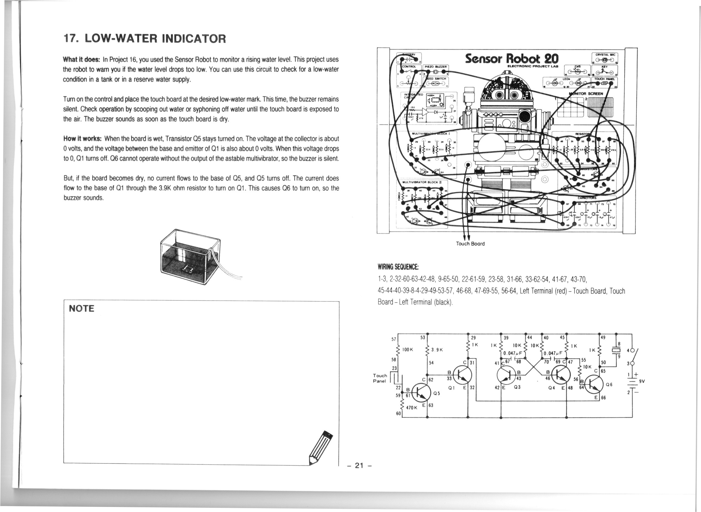
Low-Water Indicator | Project 17/20 | Maxitronix 20in1 | In The Lab With Jay Jay
This post is part of my video blog and you can find more information about this video over here.
You can support this channel on Patreon: patreon.com/JohnElliotV
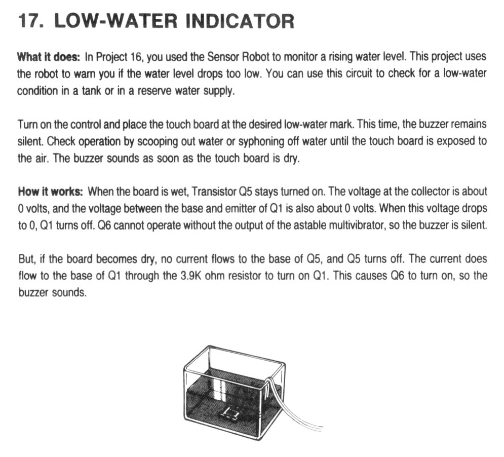
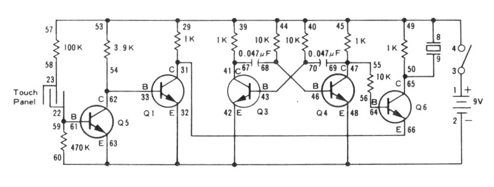
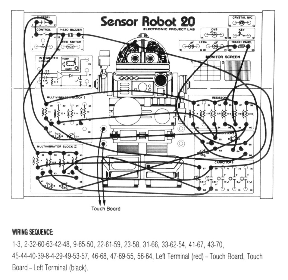
In this video we do the 17th project from the Maxitronix Sensor Robot 20 (20in1) Electronics Project Lab Kit: Low-Water Indicator.
We use the Rigol MSO5074 Mixed Signal Oscilloscope to see the output of the astable multivibrator. In the video I make a mistake and attach the probe to the wrong pins.
We use the METCAL PS-900 Soldering Station to solder the wires I use for the banana plugs I attach to the touch sensor an voice sensor (microphone).
We use the UNI-T UTi260B Thermal Imager to look at the heat profile of the circuit. We see that the low resistances (470Ω and 1KΩ) get the warmest, but the higher resistances (e.g. 10KΩ) are also slightly visible.
We use the Fluke 17B+ Digital Multimeter to check the resistance of the touch sensor.
We use the Peak Electronic Design Atlas LCR45 LCR Meter to measure the resistance of the resistor we use in the LED attachment circuit. This extra circuit allows us to switch out the buzzer for an LED, which makes a lot less racket. The resistor it uses turned out to be 470Ω.
We use the Riden RD6006 Bench Power Supply to provide 9V for our test circuit. Usually I take a current reading to see how much power the circuit draws in its various states, but I forgot!
We use the Horusdy Soldering Station with Hot Air Gun for its hot air gun in order to shrink the heat shrink which we added to the banana plug cables we attached to our sensors.
Thanks very much for watching! And please remember to hit like and subscribe! :)
Following is a product I use picked at random from my collection which may appear in my videos. Clicking through on this to find and click on the green affiliate links before purchasing from eBay or AliExpress is a great way to support the channel at no cost to you. Thanks!
Yum Cha 9-Inch Needle Nose Pliers notes notes |
Let’s go shopping!
Interlude #11: Playing with WeAct Studio Epaper Modules on ESP32-C3 MCU | In The Lab With Jay Jay
This post is part of my video blog and you can find more information about this video over here.
You can support this channel on Patreon: patreon.com/JohnElliotV
In this video we play around with the 2.13″ and 2.9″ WeAct Studio Epaper Modules available here: WeAct 2.9” 2.13″ 2.9 2.13 Inch Epaper Module E-paper E-Ink EInk Display Screen SPI Black-White Black-White-Red.
As I mention in the video I was having a hard time getting good solder joints from my Horusdy Soldering Station. This was annoying me so much that I went and purchased a new soldering iron! My new iron is an Metcal PS-900 Soldering Station and I love it! This is what a soldering iron should be!
We use the Arduino IDE and the sample code from WeAct Studio but we don’t successfully load content into our Epaper Module.
We use the Rigol MSO5074 Mixed Signal Oscilloscope to and the Rigol PLA2216 Logic Probe to wire up a Logic Analyzer to instrument out circuit, but we don’t follow through with that in the end. We run out of time. We will try again another day.
Thanks very much for watching! And please remember to hit like and subscribe! :)
Following is a product I use picked at random from my collection which may appear in my videos. Clicking through on this to find and click on the green affiliate links before purchasing from eBay or AliExpress is a great way to support the channel at no cost to you. Thanks!
Yum Cha 58-pcs Stainless Steel Thread Pitch Gauge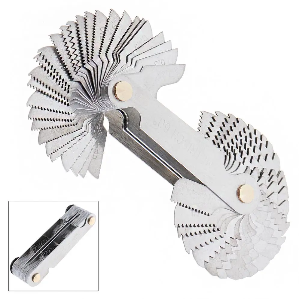 notes notes |
Let’s go shopping!
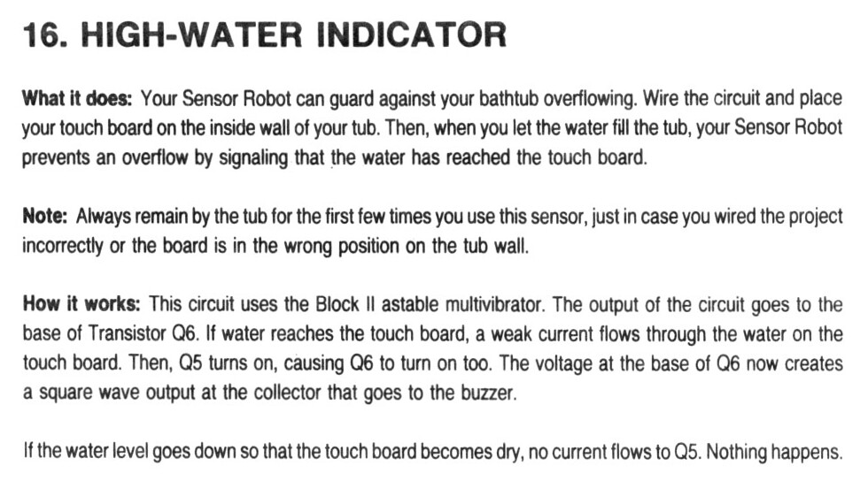
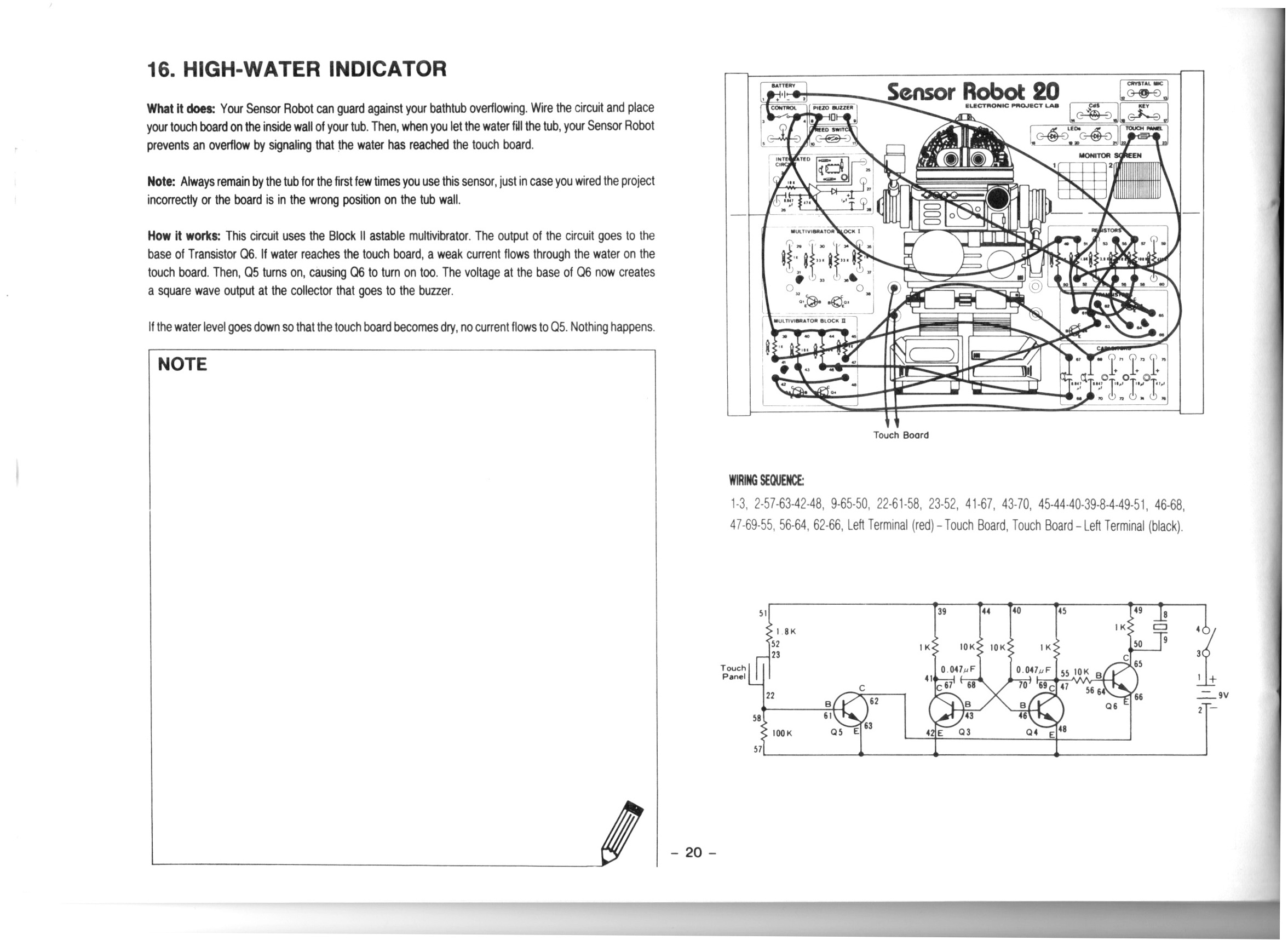
High-Water Indicator | Project 16/20 | Maxitronix 20in1 | In The Lab With Jay Jay
This post is part of my video blog and you can find more information about this video over here.
You can support this channel on Patreon: patreon.com/JohnElliotV
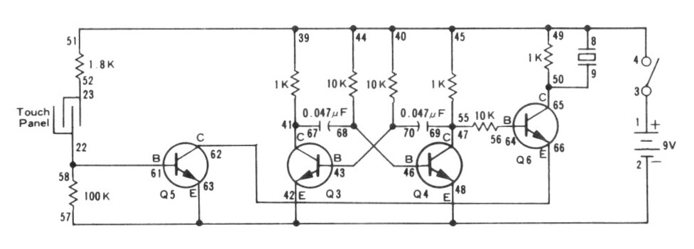
In this video we do the 16th project from the Maxitronix Sensor Robot 20 (20in1) Electronics Project Lab Kit: High-Water Indicator.
After we build the circuit we dump the sensor in a glass of water which causes the alarm to trigger. To avoid the obnoxious noise we put an LED in place of the buzzer.
Please be aware: while talking about this circuit I said that the astable multivibrator “flip flops” between states. And that’s kind of true in one sense, but I should be clear than an astable multivibrator is not a “flip flop” circuit. A flip flop circuit is a different type of circuit known as a bistable multivibrator, which is a different kind of thing. In this experiment we use an astable multivibrator to generate a 1.62 kHz square wave which provides our tone, we do not use a flip flop or bistable multivibrator circuit.
We use the Rigol MSO5074 Mixed Signal Oscilloscope to measure and visualize the 1.62 kHz square wave which generates our tone.
We use the UNI-T UTi260B Thermal Imager to investigate the circuit thermals. We see that the 1K resistors in the astable multivibrator generate the most heat.
We use the Fluke 17B+ Digital Multimeter to measure the voltage across Q5. Between about 500 mV and 750 mV is enough voltage to enable the output.
We use the Riden RD6006 Bench Power Supply to deliver the 9V DC required for the project. We use the current measurement from the power supply to see that when the LED is active the circuit draws about 23 mA compared to about 11 mA when the LED is not active.
We use the Horusdy Soldering Station with Hot Air Gun to dry the sensor after it got wet.
Thanks very much for watching! And please remember to hit like and subscribe! :)
Following is a product I use picked at random from my collection which may appear in my videos. Clicking through on this to find and click on the green affiliate links before purchasing from eBay or AliExpress is a great way to support the channel at no cost to you. Thanks!
Ausum 25 In 1 Precision Screwdriver Set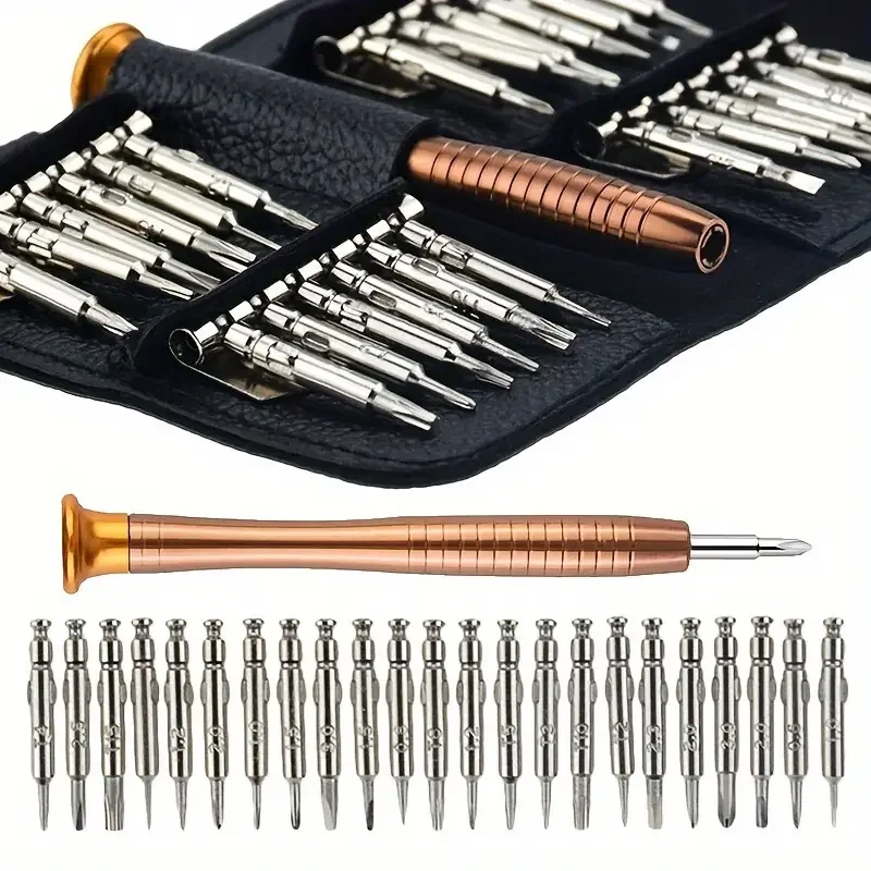 notes notes |
Let’s go shopping!
Measuring Input Impedance of MSO5074
Over here I asked about the measurements I was getting when I tried to measure the input impedance of my scope with my multimeter.
I was getting a reading I didn’t expect or understand, but that turned out to be because of a dud BNC to banana adapter that I was using.
For some reason this adapter had either a 1.5 MΩ or a 6 MΩ resistance across it. It would change from time to time when I plugged in banana plugs. Weird. I can only assume some sort of manufacturing problem.
I threw the adapter in the bin and measured again with functional equipment and got the reading of 1 MΩ that I was expecting.

