Thanks very much for watching! And please remember to hit like and subscribe! :)
Following is a product I use picked at random from my collection which may appear in my videos. Clicking through on this to find and click on the green affiliate links before purchasing from eBay or AliExpress is a great way to support the channel at no cost to you. Thanks!
Thanks very much for watching! And please remember to hit like and subscribe! :)
p.s. today I added Rigol and Imager to my spell check.
Following is a product I use picked at random from my collection which may appear in my videos. Clicking through on this to find and click on the green affiliate links before purchasing from eBay or AliExpress is a great way to support the channel at no cost to you. Thanks!
Thanks very much for watching! And please remember to hit like and subscribe! :)
Following is a product I use picked at random from my collection which may appear in my videos. Clicking through on this to find and click on the green affiliate links before purchasing from eBay or AliExpress is a great way to support the channel at no cost to you. Thanks!
Silly Job Title: Current Conjurer. I am the Current Conjurer!
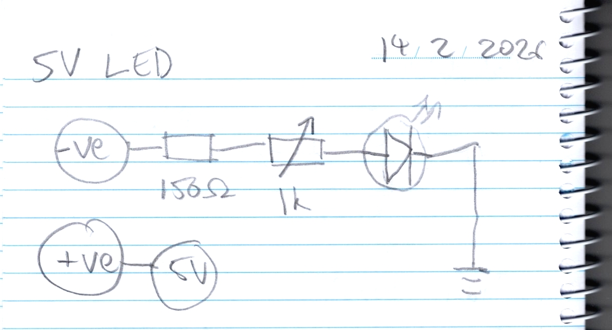
In this video we build a variable brightness LED for use as a circuit for testing an ammeter which we will be making next week as we continue through Learning the Art of Electronics. This circuit will draw between 3 and 18 mA which should meet our requirements.
This humble build shows how to make a simple circuit from components connected to each other with DuPont cables, no circuit board required. Using the DuPont cables allows us to make the circuit in the air first for assembly and testing then allowing it to be installed in the project box piece by piece after it has been tested.
During testing we discover a problem whereby the circuit doesn’t power on. Investigation with the voltmeter indicates the problem is in the wiring of the DC barrel power socket. Once that gets fixed the circuit works and is ready for installation.
The convention I used to help me remember what connects to what is that a male DuPont connection is for an output and a female DuPont connection is for an input; things which connect to each other will preferably have the same colour wire.
After testing I use heat shrink around the various leads and wires. I also use a number of different sizes of drill bit in order to make the holes in the project box for the DC barrel power in, LED, potentiometer, and banana sockets.
The DC barrel power in, potentiometer, and banana sockets are bolted in with washers and nuts, whereas the LED is held in place with hot glue. If I need to remove the LED in future isopropyl alcohol is the antidote for hot glue.
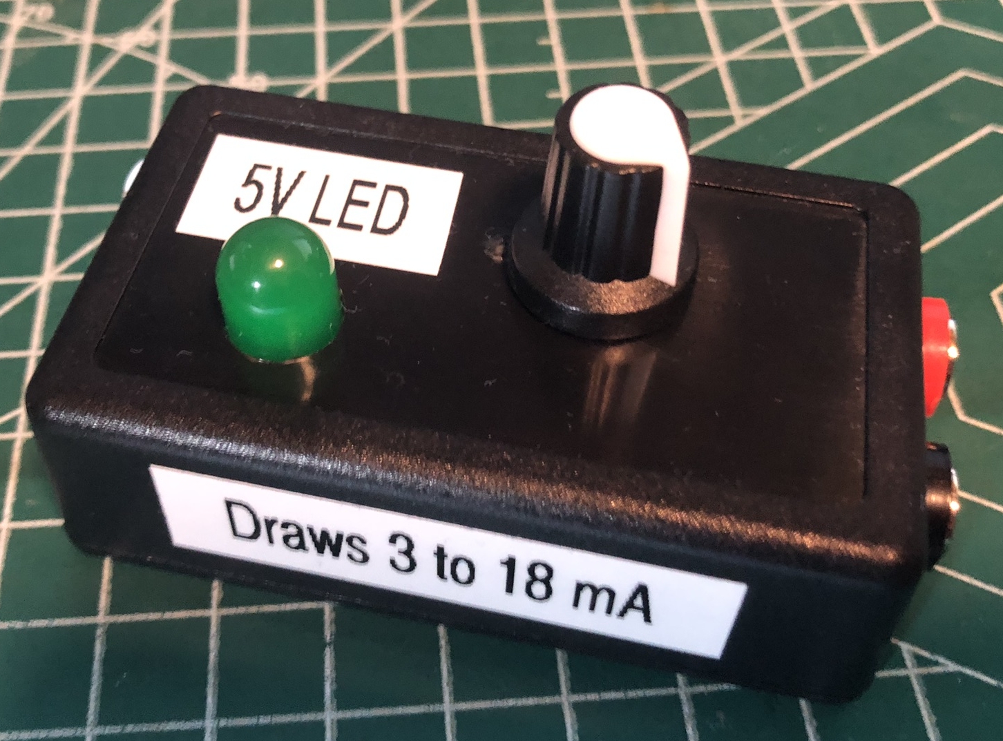
I labeled the box as “5V LED”, which should help me remember what this thing does so I can use it again in the future, should I find myself needing to draw a few milliamps in a pinch.
The circuit diagram looks something like this:
And the finished product looks something like this:
Thanks very much for watching! And please remember to hit like and subscribe! :)
p.s. today I added potentiometer, isopropyl, milliamps, multimeter, and tweezering to my spell check.
Following is a product I use picked at random from my collection which may appear in my videos. Clicking through on this to find and click on the green affiliate links before purchasing from eBay or AliExpress is a great way to support the channel at no cost to you. Thanks!
I got some feedback from a viewer about an old project: 1-Transistor Radio | Project 5/10 | Maxitronix 10in1 | Learning Electronics In The Lab With Jay Jay. The observation was that there was a discrepancy in the instructions. So in this video I redo the project to see if we can get the radio to work if we wire it the other way. Alas, we don’t, but it was worth a shot. Thanks @Panthraz for your suggestion!
Thanks very much for watching! And please remember to hit like and subscribe! :)
Following is a product I use picked at random from my collection which may appear in my videos. Clicking through on this to find and click on the green affiliate links before purchasing from eBay or AliExpress is a great way to support the channel at no cost to you. Thanks!
Silly Job Title: Grounding Genius. I am the Grounding Genius!
In this video we continue to work through our Maxitronix 30in1, today doing project #8: The Slow Motion Sunrise-Sunset Light. In this project we see how an electrolytic capacitor can control a Darlington pair.
We use the UNI-T UTi260B Thermal Imager to examine the thermal properties of the circuit (there’s not much to see).
Thanks very much for watching! And please remember to hit like and subscribe! :)
Following is a product I use picked at random from my collection which may appear in my videos. Clicking through on this to find and click on the green affiliate links before purchasing from eBay or AliExpress is a great way to support the channel at no cost to you. Thanks!
We have a look at the video cameras we currently have deployed in the studio. We have OBS Studio running on four different computers with camera inputs like this:
Thanks very much for watching! And please remember to hit like and subscribe! :)
Following is a product I use picked at random from my collection which may appear in my videos. Clicking through on this to find and click on the green affiliate links before purchasing from eBay or AliExpress is a great way to support the channel at no cost to you. Thanks!
Silly Job Title: Systems Architect. I am the Systems Architect!
In this video we continue to work through our Maxitronix 30in1, today doing project #7: The Sunrise-Sunset Light. In this project we see how an electrolytic capacitor can control and NPN transistor. By varying the resistor and capacitor we can change the timings of the circuit.
Thanks very much for watching! And please remember to hit like and subscribe! :)
Following is a product I use picked at random from my collection which may appear in my videos. Clicking through on this to find and click on the green affiliate links before purchasing from eBay or AliExpress is a great way to support the channel at no cost to you. Thanks!
In this video we make six cables: connecting banana plugs to hook clips. In order to do this we cut three banana plug cables in half and solder on hook clips to each half, leaving us with six cables.
Thanks very much for watching! And please remember to hit like and subscribe! :)
Following is a product I use picked at random from my collection which may appear in my videos. Clicking through on this to find and click on the green affiliate links before purchasing from eBay or AliExpress is a great way to support the channel at no cost to you. Thanks!
In this video we continue to work through our Maxitronix 30in1, today doing project #6: The Transistor and “Amplification”. In this project we see how an NPN transistor acts as an amplifier.
The HFR trigger coupling I use at the end of the video is called High Frequency Reject, it hides high frequency components from the triggering system and in this case fixed our triggering issue. I haven’t used HFR trigger coupling before. The Rigol user manual for the MSO5000 series doesn’t explain the feature, it just says: “HFR: rejects the high frequency components”.
We use the UNI-T UTG962E Signal Generator to provide an input signal, but we couldn’t get it to work properly so we used the signal generate from the scope instead.
Thanks very much for watching! And please remember to hit like and subscribe! :)
Following is a product I use picked at random from my collection which may appear in my videos. Clicking through on this to find and click on the green affiliate links before purchasing from eBay or AliExpress is a great way to support the channel at no cost to you. Thanks!